
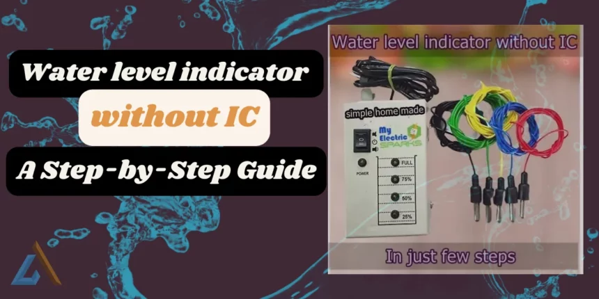
Water tank overflow can be a frustrating and wasteful problem. If you are someone who is not familiar with engineering solutions like ball valves, there is an easy and affordable solution that you can make yourself – the Water Level Indicator.
What is a Water Level Indicator?
A Water Level Indicator is an intelligent project that can detect and indicate the different water levels in a water tank or any other container. This device works by using a set of four probes that are placed at nine different levels in the container. The probes are placed in ascending order of height, with one probe being the common probe (which carries the supply) placed at the bottom of the container.
- What is a Water Level Indicator?
- What Are the Benefits of a Water Level Indicator?
- Principles of Water Level Indicator:
- How does the Water Level Indicator work?
- Circuit Diagram:
- Step by step procedure to make the Water level indicator:
- How Water Level Indicators Have Evolved to Help Conserve Water
- New Developments in Water Level Indicators
- Integration of IoT Technology
- Positive Reviews from Tech Websites
- Advantages and Disadvantages of Water Level Indicators
- More stories:
What Are the Benefits of a Water Level Indicator?
The Water Level Indicator is an easy and affordable solution that anyone can make with simple steps and a low cost of just around $1. With this device, you can prevent water wastage by detecting the water level in your container and raising the alarm when the tank is full or at any level you prefer.
“The Water Level Indicator is a simple and effective solution that can help prevent water wastage. As an electronics engineer, I appreciate how easy it is to make and how it can be adjusted to fit any container.”
Principles of Water Level Indicator:
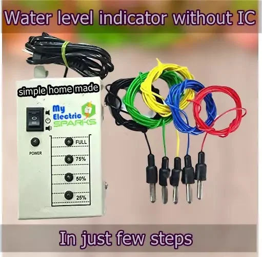
The principles behind a water level indicator are quite straightforward. A water level indicator operates using sensor probes, essentially wires that help detect the water levels in a storage tank or container.
These probes are connected to an LED light, which lights up in different ways to indicate the water level in the container. When the water level in the container reaches a certain point, an alarm or indicator is activated to alert the user that the container is full and needs to be emptied.
Overall, the principles of a water level indicator are simple and easy to understand. With this device, you can easily monitor and control the water levels in your storage tank or container, preventing water wastage and promoting the efficient use of this valuable resource.
How does the Water Level Indicator work?
The circuit is designed to show four different levels of water stored in the tank – low, medium, half, and complete but not overflowing. You can also customize the settings according to your preferences.
When the water tank is empty, a red LED will light up. As the water level increases and reaches the medium level, the contact wires get shorted as water acts as a conducting medium between wires one and 2. The green LED starts to glow, which depends on which LED is connected to the water tank.
As the water level rises and reaches half of the tank or container, another wire of LED will get into contact with water and receive a small voltage from the connected battery. As a result, the yellow LED will light up.
When the water in the tank reaches the full level, another green LED will turn on. At this point, the red LED will light up, and a buzzer will also sound to indicate that the tank is complete and the water pump or motor should be turned off to prevent water wastage. The buzzer can also be connected to a low level, depending on your requirements.
In summary, the Water Level Indicator uses sensor probes or wires to detect the water levels in the tank and send this information to different LEDs and a buzzer to indicate the water level. This device can help you control the amount of water you use and prevent the wastage of this precious resource.
suggested How to Make Your Own Automatic Hand Sanitizer Dispenser Without Arduino: A Step-by-Step Guide
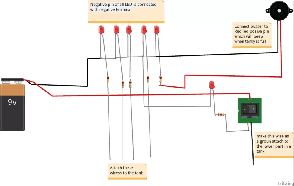
Circuit Diagram:
The circuit diagram for the water level indicator is given below.
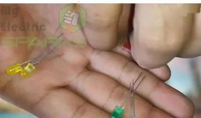
Components Required For Water Level Indicator Device :
The components list is given below; ensure that the resister value depends on the supply. If you are using 6v or 7v, or 9v, you can change the resister value because the resister glow will increase. In my case, I have used a 12v battery, that’s why the output is 1k. If your supply is less, you may use a 500-ohms or 600-ohms check, which suits your requirements.
Step by step procedure to make the Water level indicator:
The step by step procedure is as follows.
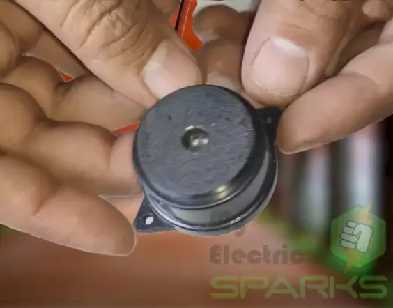
First, arrange components according to the list above. Then connect the buzzer, which will make a sound when the water tank is full.
Next, you must connect the components according to the circuit diagram provided. The circuit diagram shows how to connect the resistors, LEDs, buzzers, and probes to the battery.
Any color LEDs should be used. LED colors are not specified.
Finally, when the water tank is full, the green LED will glow again, and the buzzer will sound to indicate that the tank is full, and the water pump or motor should be turned off to prevent water wastage.
Now Add switch
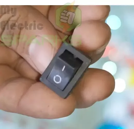
This type of switch has three pins, where one pin is common, and the other two are normally open and closed. When the switch is in its normal position, the common pin is connected to the normally open pin. When the switch is toggled or moved, the common pin connects to the normally closed pin instead.
An SPDT switch in this water level indicator circuit can help easily control the alarm or buzzer when the water tank is full or empty.
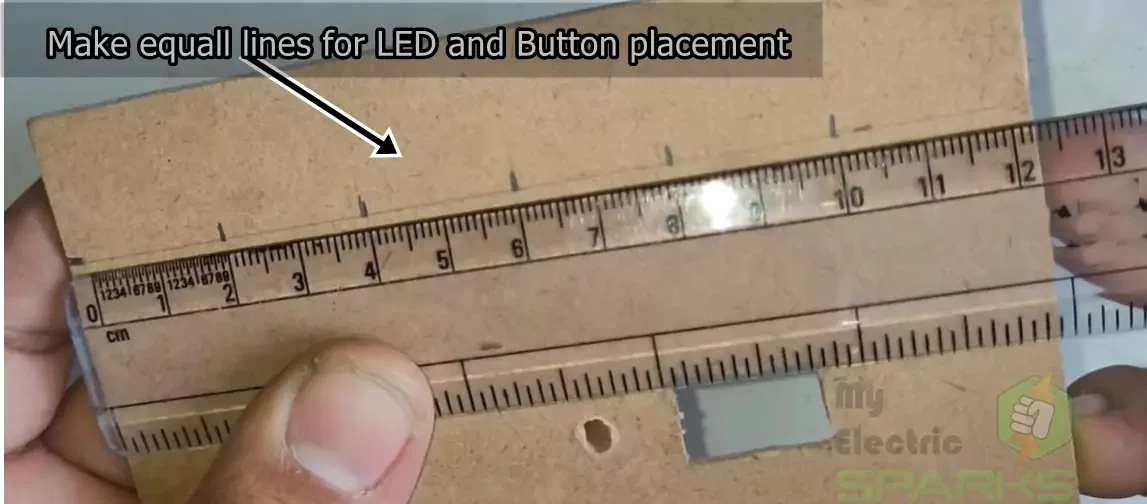
Scaling and measurements for LEDs
You can use a ruler or other measuring tool to scale the LEDs to measure the distance between the probes or wires. Then, based on that measurement, you can calculate the distance between the LEDs. For example, if the distance between the first and second probe is 2 inches, you can place the first LED 1 inch above the first probe and the second LED 1 inch above the second probe.
Now place all the components in the desired places.
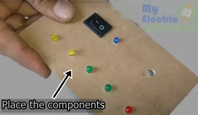
To ensure a good fit, you may need to trim or cut some parts to fit the specific components that you are using. Take your time and make sure everything is secure before moving on to the next step.
Attach the buzzer

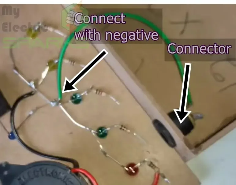
Choosing and Connecting a Connector
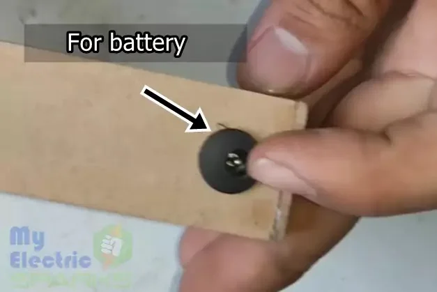
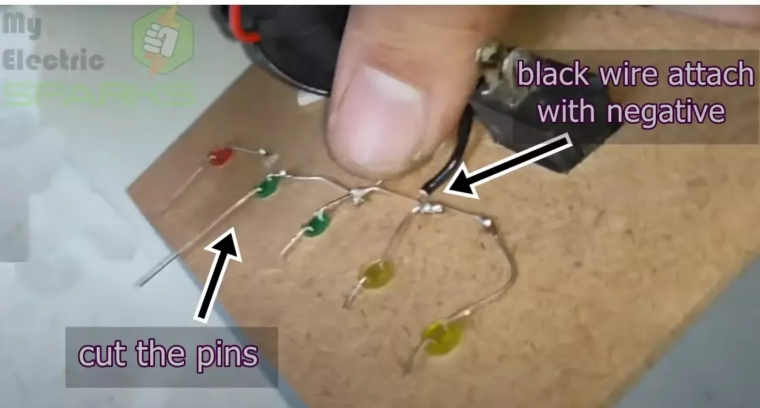
Connect and bend all the negative wires as shown.
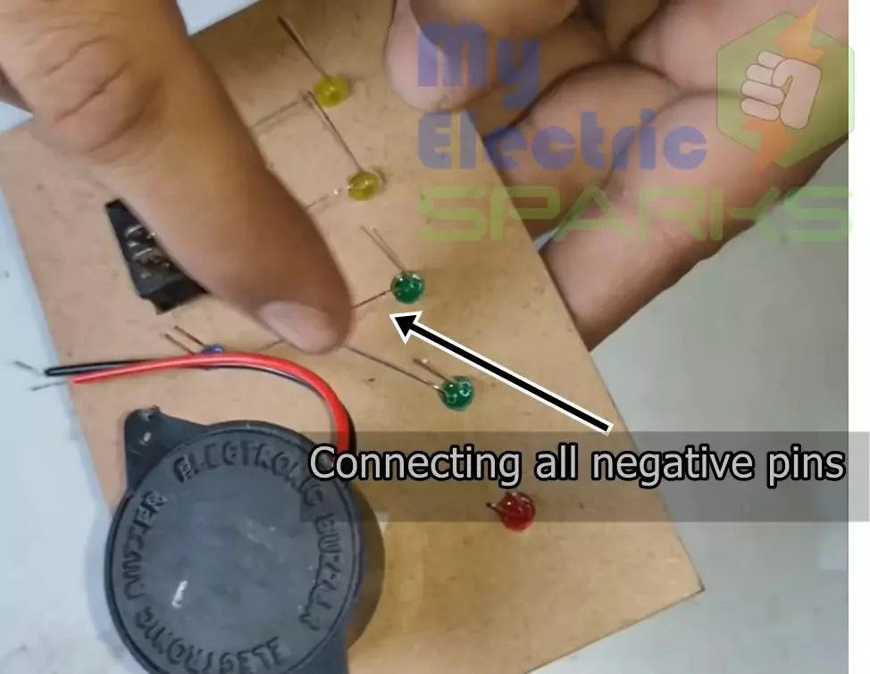
Connecting the Negative Wires of the LEDs:
Follow the diagram to connect the negative wires of the LEDs. The negative wires of the LEDs should be connected in series, as shown in the diagram.
Connect the positive wires of the LEDs and the buzzer.
Next, connect the positive wire of the second LED to the junction of the 1k resistor and the positive rail of the breadboard. Repeat this process for the remaining LEDs, making sure that each positive wire is connected to the previous LED’s junction point.
Finally, connect the positive wire of the buzzer to the junction point of the last LED and its resistor. Make sure that all connections are secure and tight.
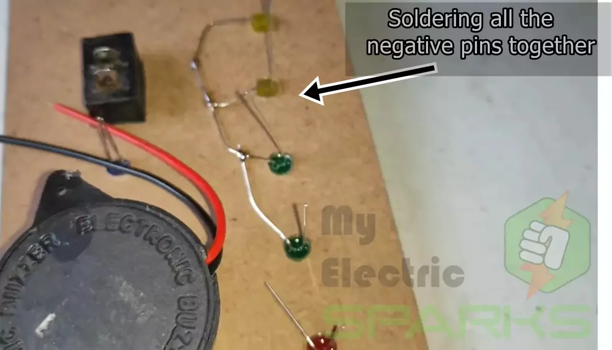
Cutting and soldering the LED pins
Once the pins are cut to the desired length, you can start soldering them. Soldering is the melting of a metal alloy onto two or more metal surfaces to join them. It’s essential to have a good soldering iron and some soldering wire to complete this step.
First, heat the soldering iron and apply a small amount of solder to the tip. Then, place the LED pins on the circuit board and touch the soldering iron to the pin and the copper pad. Hold the soldering iron in place for a few seconds until the solder melts and flows onto the connection
.
Repeat this process for all LED pins, ensuring that each connection is secure and the LED is properly aligned. Be careful to avoid creating solder bridges or connections between two or more pins that are not supposed to be connected.
Once all the LEDs are securely soldered, you can move on to the next step.
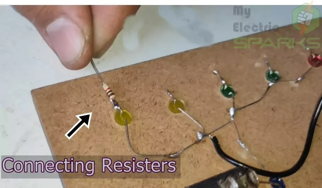
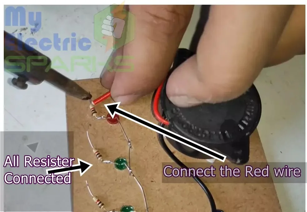
Connect Resisters to each Led
A low-value resister may lead LED to be fused, so precaution should be taken before using any resister.
Connect the Red wire of the buzzer
Now Connect one wire of the Connector to the negative wire of the LEDs.
Connect the other leg of the blue LED with a resistor
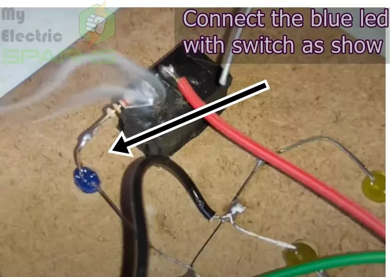
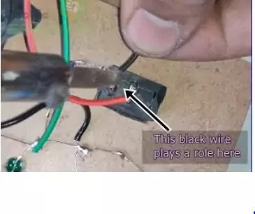
Now connect a black wire with the switch
Making this project work with the steps is very important.
In the end, connect a black wire with the switch and put it at the bottom of the container as this wire decides the current flow in the circuit of the water level indicator.
Then connect all the wires (probes) to the resister as these probes will decide the level of the water tank.
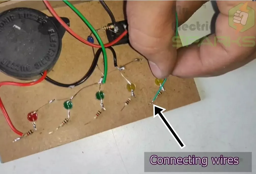
The connection should be done according to the figure below.
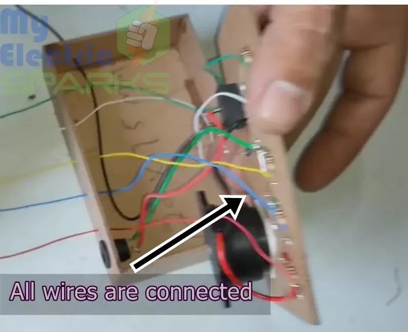
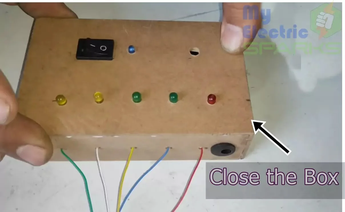
Close the box with care and connect all the wires to the level of the tank as each wire gives a different level signals.
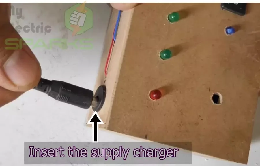
Connect the supply as shown in the figure below.
In the end, Test the circuit and it will work exactly according to our criteria.
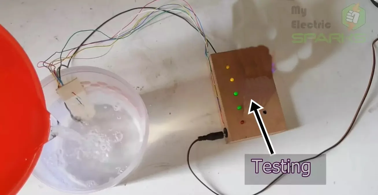
It’s done. Now you don’t need to check your water tank level this device will do it’s work and will decrease your chores.
How Water Level Indicators Have Evolved to Help Conserve Water
Water scarcity is a growing concern worldwide, and conserving water has become more important than ever. To help with this, water level indicators have been developed to help people monitor their water usage and prevent water wastage.
suggested DIY Heartbeat Sensor Using Arduino and LCD Display: A Step-by-Step Guide
New Developments in Water Level Indicators
In recent years, new developments in water level indicator technology have emerged. For example, some water level indicators now come equipped with sensors that can detect leaks in the water tank, alerting the user to potential issues before they become significant problems.
Integration of IoT Technology
Another significant development is the integration of IoT (Internet of Things) technology into water level indicators. This technology allows users to monitor their water levels remotely via their smartphone or computer, giving them real-time information on their water usage. This makes it easier for users to manage their water usage and conserve water, even when away from home.
Positive Reviews from Tech Websites
With the evolution of water level indicators, tech websites have started reviewing these devices to highlight their features, performance, and ease of use. These reviews can help consumers decide when to select a water level indicator that best suits their needs.
Overall, water level indicators have come a long way since their inception, and their evolution has made it easier for people to conserve water. With the integration of IoT technology and positive reviews from tech websites, water level indicators have become an essential tool for water conservation in 2023.
Advantages and Disadvantages of Water Level Indicators
Water level indicators, also known as water level controls, offer numerous benefits, including:
- Power Saver: With the need for energy conservation, water level controllers help save power by limiting electricity usage and water needed to regulate the supply.
- Money Saver: These devices help save money by reducing the wastage of water and electricity while accurately regulating energy usage, leading to substantial savings over time.
- Automatic: Water level controllers function automatically, eliminating the need for manual monitoring and regulation.
- Water Maximization: The water level controller maximizes water usage during midday and lessens water usage at night, ensuring the appropriate water level is maintained at all times.
- Reliable Electronic Design: The solid-state electronics in newer models minimize durability issues while creating considerable savings in the unit’s lifespan with an advanced modular design.
- New Control Minimize Fouling & Deterioration: Solid-state electronics minimize mineral fouling, plating, rusting, and deterioration of probes, extending the lifespan of the controllers.
- Easy Installation with LED Monitoring: The integrated firmware and digital dry-contact circuitry offer superior performance and hassle-free installation. LED lights provide straightforward monitoring and verification of proper operation.
Disadvantages of Water Level Indicators
Some drawbacks of water level indicators and float switches include the need for replacement every three years due to rust, fouling, and deterioration and the absence of LED indicator lights and warranties.
More stories:
Password-Based Door Lock System Using Arduino: A Step-by-Step GuideBuild Your Own Wi-fi Controlled Robot Car Using NodeMcu: A Fun and Easy DIY Project
Solar Tracking device project: A Step-by-Step Guide: Water level indicator without IC:A Step-by-Step Guide


I love what you guys are usually up too. This kind of clever
work and coverage! Keep up the good works