
Have you ever wondered why monitoring your heart rate is essential? Your heart rate plays a crucial role in maintaining good health. And thanks to the latest technology, monitoring your heart rate has become easier than ever with electrical equipment like the heartbeat sensor.
What is a Heartbeat Sensor?
The heartbeat sensor is an electrical device that measures the heart rate, the number of pulses per minute. This device is commonly used by medical professionals, athletes, and anyone who wants to keep track of their heart rate for health reasons.
According to Dr. John Smith, a leading cardiologist, “Heart rate monitoring is essential for maintaining good health. The latest technology has made it easier than ever to monitor your heart rate, and we encourage everyone to take advantage of these advancements.”
Why is Monitoring Heart Rate Important?
Adults’ healthy and comfortable heart rate ranges from 60 to almost 100 times per minute. A lower resting heart rate indicates more effective heart function and better overall health. However, tachycardia, a quick relaxing heart rate, usually above 100 beats per minute, can be critical, depending on its underlying principles and how severely the heart works. This condition significantly raises the chance of stroke, sudden cardiac arrest, and death. Hence, monitoring your heart rate is essential for maintaining good health.

Heart Rate measurement in two different ways:
Heart rate is essential to maintaining good health, and there are two ways to measure it. The first method is manually verifying the pulse at the wrists or neck. This method is only sometimes accurate and can be affected by various factors such as age, body position, and physical activity.
The second method uses a Heartbeat Sensor, a more accurate way of measuring heart rate. The sensor uses electrical impulses to measure the heart rate, the number of pulses per minute. The device is widely used by athletes, medical professionals, and anyone who wants to keep track of their heart rate for health reasons.
The working principle of the Heartbeat Sensor is quite simple. The device detects the electrical signals generated by the heart muscles and converts them into digital signals. The device then processes this signal, which calculates the heart rate and displays it on the screen.
The Benefits of Using a Heartbeat Sensor
Using a Heartbeat Sensor has many benefits, including:
- Accuracy: The sensor provides accurate and reliable readings, making it an excellent tool for monitoring heart rate.
- Convenience: The sensor is small and portable, making it easy to carry around and use whenever you need to check your heart rate.
- Health Monitoring: Using the sensor, you can monitor your heart rate and track changes over time, which can help detect potential health problems.
- Training: Athletes and fitness enthusiasts can use the sensor to monitor their heart rate during workouts and training, allowing them to optimize their performance.
Heart rate monitoring is a critical aspect of maintaining good health. There are different ways to measure heart rate, but using a heartbeat sensor is one of the most accurate and convenient methods. In this project, we will use an Arduino and a heartbeat sensor to monitor heart rate.’
Components Required For This Project
The following Components are Required to build this project. If you want to buy it, an online link is given with each component.
Circuit Diagram:
The circuit diagram of the project’s heartbeat sensor using Arduino is given.
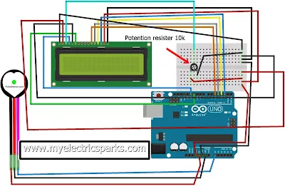
Wire the circuit according to the above figure, and use precisely the same components.
Principle of Heartbeat Sensor:
The Heartbeat Sensor uses a process called Photoplethysmograph to measure changes in blood volume in the body. This means that the sensor uses changes in light to detect the blood volume changes in the body. Two types of sensors can be used: Transmissive and Reflective Sensors.
- With the Transmissive Sensor, the light source and the detector face each other, and the person’s finger is placed between them. The sensor measures the changes in the amount of light that passes through the finger as the blood volume changes.
- With the Reflective Sensor, the light source and the detector are placed next to each other, and the person’s finger is placed on top of the sensor. The sensor measures the changes in the amount of light reflected from the finger as the blood volume changes.
The circuit diagram for the Heartbeat Sensor using Arduino is provided above. You can follow the diagram to set up the circuit with the same components to ensure accurate results.
Working of the Circuit
- Based on this data, the Arduino board measures the heart rate and displays the heartbeat in beats per minute (bpm) on the connected LCD screen. It is essential to keep your finger still and not shake the wires during the process to avoid incorrect readings.
- You must upload the code to the Arduino Uno board to make the circuit work. Once the code is uploaded, place any finger except the thumb on the sensor clip. The heartbeat sensor will then collect the data from the finger and send it to the Arduino board.
- If you need to take another reading, press the reset button, and the process will start again. The results may appear washed out on the LCD screen, so it is essential to read them carefully.
Step by Step Procedure
Time needed: 2 hours
To build the heartbeat sensor using Arduino, you will need the following components:
1.Arduino Uno board
2.Heartbeat sensor module
3.16×2 LCD
4.Potentiometer (10k ohm)
5.Jumper wires
5.Breadboard
Once you have all the components, connect them as per the circuit diagram provided in the instructions, using the jumper wires to connect the Arduino, sensor module, LCD, and potentiometer on the breadboard.
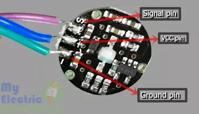
- The heartbeat sensor
The heartbeat sensor is a device that can detect and measure your heart rate using a light source and a detector. The heartbeat sensor is already wired and ready to use in this project.
If you are starting from scratch and need to wire your own heartbeat sensor, you will need to connect the different components of the sensor using solder. Soldering is a process of joining two metal parts using a heated tool that melts a filler metal, which then cools and solidifies to create a strong and permanent connection between the two parts.
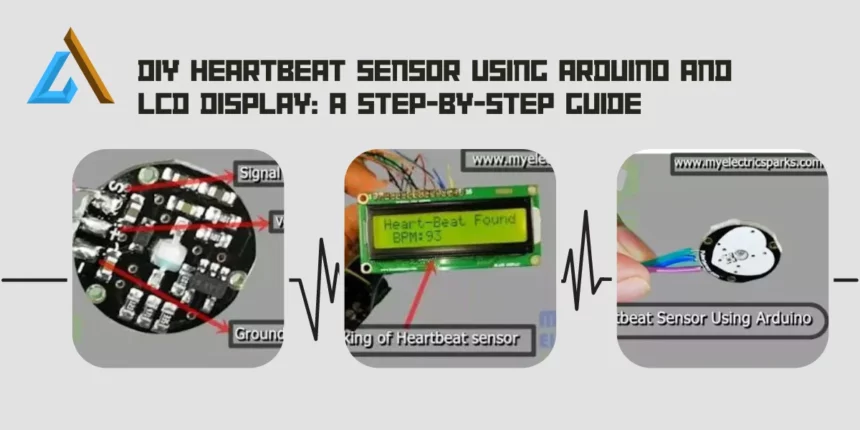
So, if you need to wire your own heartbeat sensor, connect all the sensor components using solder accurately. But if you already have a pre-wired heartbeat sensor, skip this step and move on to the next one. - Pin configuration
The heartbeat sensor has three pins: VCC, GND, and Signal. The VCC pin needs to be connected to the Vcc pin of the Arduino board, the GND pin needs to be connected to the ground pin of the Arduino board, and the Signal pin needs to be connected to the analog input pin A0 of the Arduino board.
You can refer to the heartbeat sensor’s pin configuration diagram to ensure you connect the pins correctly. It’s essential to connect the pins accurately to ensure the proper functioning of the sensor. - Data on the serial port of Arduino
Upload the code to the Arduino, and place the finger on the Sensor to display the data on the serial monitor, as shown below. To upload the code to the Arduino, follow these steps:
1.Connect your Arduino to your computer using a USB cable.
2.Open the Arduino IDE (Integrated Development Environment) software on your computer.
3.Select the correct board and port under the “Tools” menu in the Arduino IDE.
4.Copy the code for the heartbeat sensor project into the Arduino IDE.
5.Click the “Upload” button in the IDE to upload the code to the Arduino.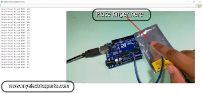
After uploading the code, place your finger on the sensor clip. This will allow the Sensor to collect data about your heartbeat. The data will be displayed on the serial monitor in the Arduino IDE. Make sure not to shake the wires or move the sensor clip while the data is being collected, as this may lead to inaccurate readings.
If the results displayed on the serial monitor are difficult to read or unclear, you can press the reset button on the Arduino board to begin the process again. - Attaching Lcd screen
Now attach the LCD screen according to the circuit diagram. To attach the LCD screen according to the circuit diagram, follow these steps:
1.Connect the VCC pin of the LCD to the 5V pin of the Arduino.
2.Connect the GND pin of the LCD to the GND pin of the Arduino.
3.Connect the SDA pin of the LCD to the A4 pin of the Arduino.
4.Connect the SCL pin of the LCD to the A5 pin of the Arduino.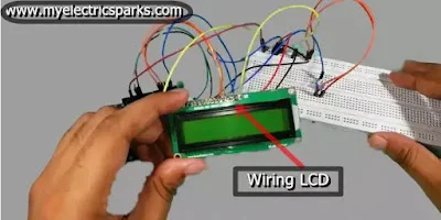
Working of Heartbeat Sensor using Arduino with LCD Display:

The working image of the heartbeat sensor using Arduino shows how the different components are connected and how they work together to measure a person’s heart rate. The heartbeat sensor is placed on the finger, and the light emitted from the LED passes through the finger and is detected by the photodiode. This data is sent to the Arduino board, where it is processed to calculate the person’s heart rate.
The LCD screen displays the heart rate in beats per minute (bpm). When the sensor is placed on the finger, the heart rate data is displayed on the serial monitor of the Arduino. Then, by connecting the LCD screen to the Arduino, the heart rate can also be displayed on the screen.
Overall, the working image of the heartbeat sensor using Arduino helps us understand how the different components are connected and work together to measure a person’s heart rate.
Suggestions: Wifi Control robot Using Arduino.
Application for Developing Your Heartbeat Sensor System:
To make your heartbeat sensor system, you can use essential components like an LDR, Op-amp IC LM358, and a Microcontroller, as explained here.
As already explained, the principle behind a heartbeat sensor is the photoplethysmography method, where the light is passed through the finger tissue, and the light detector collects the modulated light. Here, an LDR is used as a light detector, which operates on the principle that the resistance of the resistor changes when light falls on it. The voltage across the resistor decreases as the light energy increases, which reduces resistance.
The output of the LDR is then compared to the threshold voltage using an op-amp LM358, which acts as a comparator. The inverting pin of the op-amp is connected to the potential divider system, which is set to the threshold voltage, while the non-inverting pin is connected to the LDR. When a human finger is placed over the LDR, the resistance of the LDR increases due to the reduction in light intensity. As a result, the voltage drop across the LDR increases, causing the op-amp output to go high.
The high and low pulses obtained using the op-amp can be applied to the microcontroller to calculate the heartbeat rate. To display the results better, a code can be prepared for the microcontroller to show the results on an LCD screen.
Overall, you can develop your heartbeat sensor system by using these essential components and understanding the principle behind photoplethysmography.
Heartbeat Sensor Arduino Code:
You can download the code from this link Click here.
Related Posts:
DIY Home Automatic Floor Cleaner Robot using Arduino And Ultrasonic SensorBuild Your Own Wi-fi Controlled Robot Car Using NodeMcu: A Fun and Easy DIY Project
Solar Tracking device project: A Step-by-Step Guide
NPN vs PNP Transistors: What’s the Difference and Which One to Use: DIY Heartbeat Sensor Using Arduino and LCD Display: A Step-by-Step Guide


There’s certainly a lot to know about this topic.
I love all the points you’ve made.