
Musical rotation or musical note is a record of musical sounds or images.Sound Or a set of visual instructions for the Performance of Music. It is usually written or printed and requires a conscious efforts.We have design this project in order to detect musical note detector using arduino.
Introduction To Musical Note Detector
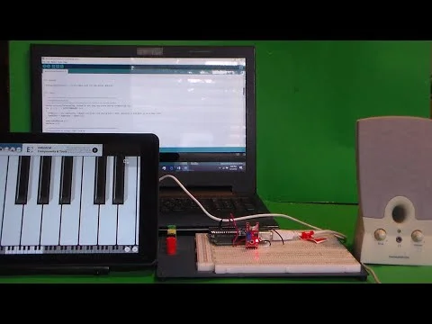
This Arduino project displays the approximate frequency, and the musical note played using an electronic keyboard. The Arduino Uno sends the analog output of the sound module detector to the A0 input. The analog signal is quantized and digitized. The first three periods are used for the calculation of fundamental frequency. This is done using auto-correlation and weighting. To determine the nearest musical note frequency, the approximate fundamental frequency can be compared with frequencies in octaves 3, 4, 5, and 5. Finally, the screen displays the closest frequency that has been guessed here this project will help you about musical note detector using Arduino.
Parts Required for Musical Note Detector
Circuit diagram
Here is the circuit diagram make sure to use exactly the same wiring incase of any problem or error you can comment below.

Code for Musical Note detector
#include “arduinoFFT.h”
#define SAMPLES 128 //SAMPLES-pt FFT. Must be a base 2 number. Max 128 for Arduino Uno.
#define SAMPLING_FREQUENCY 2048 //Ts = Based on Nyquist, must be 2 times the highest expected frequency.
arduinoFFT FFT = arduinoFFT();
unsigned int samplingPeriod;
unsigned long microSeconds;
double vReal[SAMPLES]; //create vector of size SAMPLES to hold real values
double vImag[SAMPLES]; //create vector of size SAMPLES to hold imaginary values
void setup()
{
Serial.begin(115200); //Baud rate for the Serial Monitor
samplingPeriod = round(1000000*(1.0/SAMPLING_FREQUENCY)); //Period in microseconds
}
void loop()
{
/*Sample SAMPLES times*/
for(int i=0; i<SAMPLES; i++)
{
microSeconds = micros(); //Returns the number of microseconds since the Arduino board began running the current script.
vReal[i] = analogRead(0); //Reads the value from analog pin 0 (A0), quantize it and save it as a real term.
vImag[i] = 0; //Makes imaginary term 0 always
/*remaining wait time between samples if necessary*/
while(micros() < (microSeconds + samplingPeriod))
{
//do nothing
}
}
/*Perform FFT on samples*/
FFT.Windowing(vReal, SAMPLES, FFT_WIN_TYP_HAMMING, FFT_FORWARD);
FFT.Compute(vReal, vImag, SAMPLES, FFT_FORWARD);
FFT.ComplexToMagnitude(vReal, vImag, SAMPLES);
/*Find peak frequency and print peak*/
double peak = FFT.MajorPeak(vReal, SAMPLES, SAMPLING_FREQUENCY);
Serial.println(peak); //Print out the most dominant frequency.
/*Script stops here. Hardware reset required.*/
while (1); //do one time
}
Flow Diagram

Testing of the code
Here is the working of the complete project incase you found any error in code or you have implemented some additional feature dont forget to share with our comunity.

Conclusion
This project has been made by one of our community member and is in working condition as you must required an arduino and smart phone also an speaker complete circuit diagram is given above.
if you want How to Interface Arduino with MALTAB? here is a suitable article for you.
For downloading the piano App Click here