
Have you ever wished that cleaning your floors could be done automatically without you having to lift a finger? The Home Automatic Floor Cleaner Robot is here to make your dreams come true!
What is it?
The Home Automatic Floor Cleaner Robot is a device that’s designed specifically for cleaning floors. It’s fully automatic, meaning it cleans your floors without human intervention. Plus, it has an auto obstacle detector that helps it navigate around objects on the floor.
How does it work?
The device is based on the Arduino platform, a cost-efficient way to build such a robot. It’s easy to adjust the settings according to your specific needs and cleans your floors quickly and efficiently.
Why is it important?
Cleaning floors can be time-consuming and tiring, especially for those with mobility issues or a busy lifestyle. The Home Automatic Floor Cleaner Robot eliminates manual labor, making cleaning your floors hassle-free and effortless.
What’s the cost?
We understand the importance of affordability, so we’re constantly striving to make this project more cost-efficient. We aim to ensure anyone can afford the Home Automatic Floor Cleaner Robot without hesitation.
So, if you’re tired of spending your time and energy cleaning your floors, try the Home Automatic Floor Cleaner Robot and enjoy a clean and hassle-free home!
Components of an Automatic Home Cleaning Robot and Their Uses.
There are a few things you need to get started with building your Automatic Home Cleaning Robot. You can buy it from given Amazon links below. Here is the list of all the things that you need to make the robot:
- Acrylic Sheets: These sheets make the robot’s frame and chassis. Acrylic is a durable and lightweight material that’s easy to work with.
- Motor Driver L298: The L298 is a motor driver that controls the speed and direction of the DC motors used in the robot. It’s a crucial component that allows the robot to move around and clean your floors.
- Arduino Board Uno R3: The Arduino board is the robot’s brain. It’s a microcontroller that receives input from the sensors and controls the DC motors. You can program the board to make the robot move in a specific direction or detect obstacles.
- Ultrasonic Sensor HC-SR04: The ultrasonic sensor detects objects and measures distances. It sends ultrasonic waves and measures how long the waves take to bounce back. This allows the robot to detect obstacles in its path and avoid them.
- Ultrafire Battery 18650 3.7V: This rechargeable battery provides power to the motors and the Arduino board. It’s a high-capacity battery that can power the robot for an extended period.
- Jumper Wire (x3): Jumper wires are used to connect the different components of the robot. They’re flexible wires with pins on each end that can be easily plugged into the Arduino board and other components.
- DC Motors (x5): DC motors drive the robot’s wheels. They’re small, powerful motors that provide the necessary torque to move the robot around.
- Wheel 65 x 26mm (x4): These wheels are attached to the DC motors and allow the robot to move around.
- Switch: The switch is used to turn the robot on and off.
These components work together to make an Automatic Home Cleaning Robot that can navigate your home and clean your floors efficiently.
Where can you get the elements for the Automatic Home Cleaning Robot?
We’ve provided links below for your convenience to help you get started.
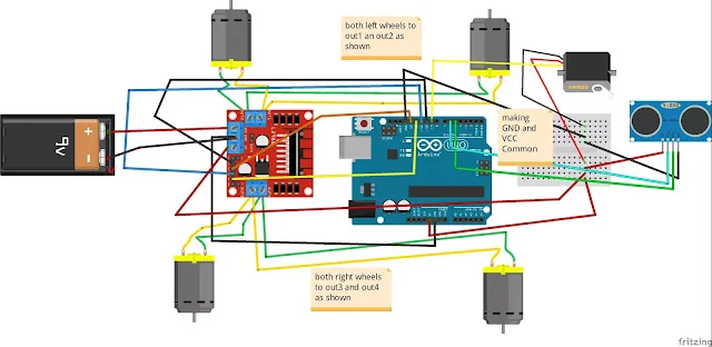
Circuit Diagram and Pin Configuration
The circuit diagram is a visual representation of how the robot’s different components are connected. It shows the wires, connections, and components in a schematic format, so you can see how they interact.
The pin configuration is a set of instructions that tells you which pins on the Arduino board to connect to the different components. Each pin has a specific function, such as providing power or receiving signals, and it’s essential to connect the pins correctly to ensure the robot works appropriately.
You’ll need to connect the different components using jumper wires to wire up the robot according to the circuit diagram. You’ll also need to connect the correct pins on the Arduino board to the correct pins on the different components.
Suggestion: Coronavirus live updater
Connection of Motors:
The motors are connected to the L298 motor driver. The two left motors are connected to the Out A of the L298, while the right two are connected to the Out B of the L298.
- Left two motor ———-> Out A of L298 .
- Right two motor ———–>Out b of L298 driver.
Connection of Motor Shield with Arduino:
The motor shield is connected to the Arduino board using jumper wires. The GND of the L298 is connected to the GND of the Arduino, and the VCC of the L298 is connected to the Vin of the Arduino. The INA or IN1 of the L298 is connected to pin 10 of the Arduino, INC or IN3 of the L298 is connected to pin 11 of the Arduino, IND or IN4 of the L298 is connected to pin 12 of the Arduino, and INB or IN2 of the L298 is connected to pin 13 of the Arduino.
- GND of L298 ————-> Gnd of Arduino
- VCC of L298 ————->Vin of Arduino
- INA or IN1 of L298———->pin 10 of Arduino.
- INC or IN3 of L298———->pin 11 of Arduino.
- IND or IN4 of L298———->pin 12 of Arduino.
- INB or IN2 of L298———->pin 13 of Arduino.
Connection of Battery:
The battery is connected to the motor shield. The red wire of the battery is connected to the 5V(Vcc) of the motor shield, while the black wire of the battery is connected to the GND of the motor shield.
- 5v(Vcc) of motor shield————>connect the red wire of the battery
- GND of motor shield —————-> connect the black cable of the battery
Connection of Servo with Arduino:
The servo is connected to the Arduino board. The brown wire of the servo is connected to the GND of the Arduino, the red wire of the servo is connected to the 5V of the Arduino, and the orange wire of the servo is connected to pin 9 of the Arduino.
- GND of Arduino—————>connect servo brown wire.
- 5v of Arduino —————->connect the red cable of servo.
- Pin 9 of Arduino —————->connect orange of.
Connection of Ultrasonic Sensor:
The ultrasonic sensor is connected to the Arduino board. The GND of the ultrasonic sensor is connected to the GND of the Arduino, and the Vcc of the ultrasonic sensor is connected to the 5V pin of the Arduino. The Echo of the ultrasonic sensor is connected to pin 5 of the Arduino, while the Trig of the ultrasonic sensor is connected to pin 6 of the Arduino.
- GND of Arduino ————> Gnd of the Ultrasonic Sensor.
- 5v pin of Arduino ———-> Vcc of the Ultrasonic Sensor.
- Pin 5 of Arduino ————-> Echo of the ultrasonic sensor.
- Pin 6 of Arduino ————-> trig of Ultrasonic sensor.
Step by Step Procedure For Home Automatic Floor Cleaner Robot
Time needed: 3 hours
The Home Automatic Floor Cleaner Robot is a device that helps to clean floors automatically. This DIY project can be built using essential electronic components and tools. The robot uses an Arduino microcontroller, motors, ultrasonic sensors, and a cleaning mechanism. The robot is designed to move around independently and clean the floor without human intervention. This project is a great way to learn about robotics and programming while creating a valuable home device. This step-by-step procedure will guide you through building your own Home Automatic Floor Cleaner Robot.
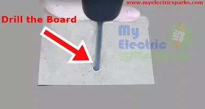
- Acrylic sheet body
Before you begin building the Home Automatic Floor Cleaner Robot, the first step is to make the robot’s body. You can create the body using acrylic sheets, which you can buy from above link . Once you have the acrylic sheet, drill it according to the diagram to ensure the proper shape and size.
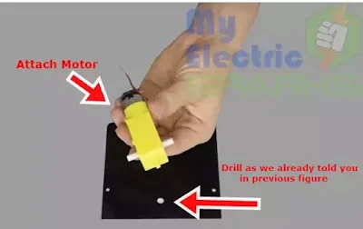
- Attaching Motors
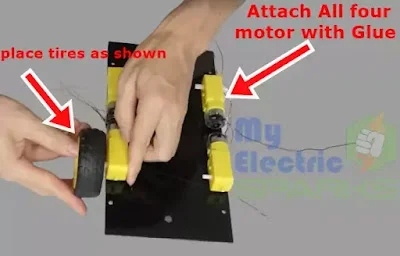
After creating the body, you need to connect the motors to the L298 motor driver. Remove the grey sheet, as it may appear black. Then, you can attach the motors using glue or drilling holes in the acrylic sheet to tighten the motors correctly.
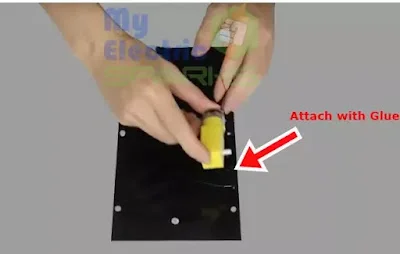
- Dc motors attaching
Once you have lifted off the grey sheet and prepared the acrylic sheet, the next step is to attach the motors using glue. You can apply a small amount of glue to the bottom of each motor and carefully place them onto the designated spots on the acrylic sheet. Let the glue dry completely before moving on to the next step.
The two left motors should be connected to the Out A of the L298 driver, while the two suitable motors should be connected to the Out B of the L298 driver. Then, connect the motor shield to the Arduino board by following the pin configuration provided above. - Attaching Wheels
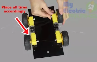
After attaching the motors, the next step is to connect the tires to them. You can do this by carefully sliding the tires onto the motors and securing them. Make sure that each tire is firmly attached to its respective motor before moving on to the next step.
- Fixing tires
Now that all the tires are fixed, you can move on to the next step of building the Home Automatic Floor Cleaner Robot.
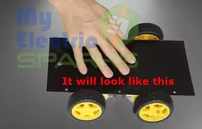
- Progress in building the Home Automatic Floor Cleaner Robot
By completing the above steps of attaching the motors and tires, you have made significant progress in building the Home Automatic Floor Cleaner Robot. However, there are still a few more steps to complete, so keep following the instructions to finish the project successfully.
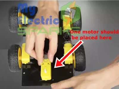
- Placing motor at the Front
The next step is to place another motor at the front of the robot. This motor will be used to control the direction of the robot. You can similarly attach the motor as the previous ones, using glue or drilling holes to tighten it. Make sure it is firmly attached and aligned with the other motors before moving on to the next step.
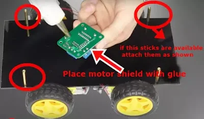
- Placing L298 Motor shield
Now attach the sticks accordingly to place the Motor shield. You can refer to the figure below to see the placement of the sticks. Attach them securely so the Motor shield is stable and does not move around. This will ensure that the robot functions properly when it is in use.
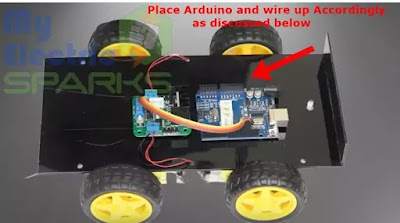
- Attaching Arduino and Motor shield Accordingly
Now you can place the Arduino board and the Motor shield onto the sticks that you have attached in the previous step. Make sure you connect the wires from the motors and the Ultrasonic sensor to the correct pins on the Motor shield and Arduino board, per the instructions provided earlier.
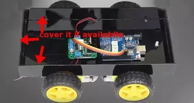
This will ensure the robot functions properly and the sensors and motors are correctly controlled. Secure the Arduino board and Motor shield in place so they do not move around during operation. - Wiring and Covering
The next step is to cover the robot fully enclosed and protected. As shown in the figure below, you can use another acrylic sheet to cover the robot. Cut the acrylic sheet to the appropriate size and shape, and then use screws or glue to attach it securely to the robot’s body.
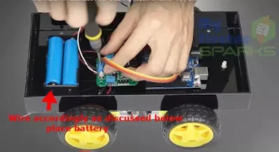
Leave enough space for the wheels to move freely and for the Ultrasonic sensor to function correctly. Once the cover is in place, your robot should look like a fully enclosed, professional device. - Placing Battery
Now it’s time to add the battery to power your robot. You can use a 3.7V Ultrafire Battery 18650 for this project. Connect the red wire of the battery to the Vcc pin of the motor shield, and connect the black wire to the GND pin of the motor shield. This will provide power to the motors and the Ultrasonic sensor.
Secure the battery so it doesn’t move around while the robot is in use. You can use tape or glue to hold it in place or create a small compartment for the battery inside the robot’s body. Once the battery is in place and wired correctly, your robot is almost ready! - Attach it to Arduino
To attach the servo motor to Arduino, follow given steps below:
1.Connect the servo motor’s brown wire to the Arduino’s GND pin.
2.Connect the red wire of the servo motor to the 5V pin of the Arduino.
3.Connect the orange wire of the servo motor to pin 9 of the Arduino.
.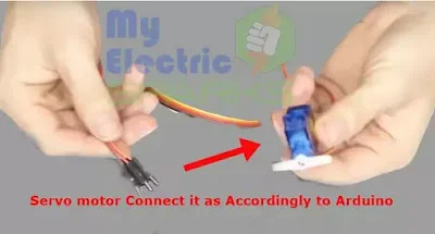
Make sure the connections are tight and secure. - Attach ultrasonic sensor with Arduino
Now attach the Ultrasonic sensor to the Arduino, follow given steps below:
1.Connect the Ultrasonic sensor’s GND pin to the Arduino’s GND pin.
2.Connect the Vcc pin of the Ultrasonic sensor to the 5V pin of the Arduino.
3.Connect the Echo pin of the Ultrasonic sensor to pin 5 of the Arduino.
4.Connect the Trig pin of the Ultrasonic sensor to pin 6 of the Arduino.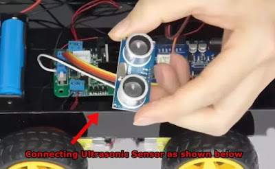
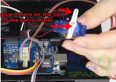
Again, make sure the connections are tight and secure. - Servo motor attaching
It’s important to note that before attaching the servo motor to the ultrasonic sensor, make sure that the servo motor is calibrated to work with the sensor. Once the calibration is done, glue the tip of the servo motor and attach it to the ultrasonic sensor. This will allow the sensor to rotate and detect obstacles in all directions.
- Attaching Ultrasonic sensor
To attach the Ultrasonic Sensor to the servo motor, you need to follow these steps:
1.Take the Ultrasonic sensor and place it on top of the servo motor, making sure that it is centered.
2.Use a small amount of glue to attach the Ultrasonic Sensor to the top of the servo motor.
3.Be careful not to use too much glue, which can cause the sensor to become unstable.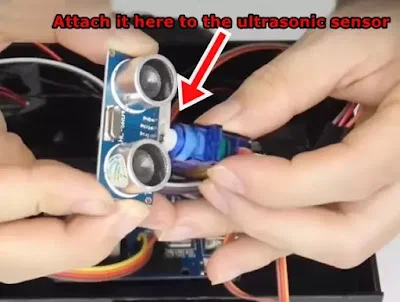
Allow the glue to dry completely before moving on to the next step.
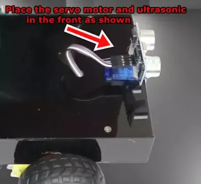
Once you have attached the Ultrasonic Sensor to the servo motor, you can proceed with the next step in building your Home Automatic Floor Cleaner Robot - Placing the sensor at the front
It is recommended to fix the ultrasonic sensor and the servo motor on the front of the home cleaning robot using screws and nuts. This will ensure they remain stable and do not fall off during operation.
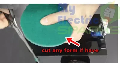
-
To make the robot move smoothly, we need to cut a round shape punch. This punch will be attached underneath the robot to move freely without any resistance. The punch should be cut in a circular shape to fit perfectly under the robot.
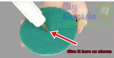
- Glue the punch as shown
After cutting the round punch, glue it to the bottom of the Home Cleaning Robot. This will help the robot move around smoothly and without damaging the surface.
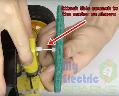
- Attaching motor
After gluing the round punch, fix it underneath the Home cleaning robot and attach it to the motor permanently, as shown in the figure. This punch will help clean the floor by pushing dirt or debris toward the vacuum cleaner.
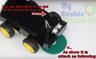
- Switch and Punch Attach
To make the Home cleaning robot move around easily, we need to fix a round punch underneath it. This punch should be connected to a motor that can move quickly and without hesitation. Make sure to connect the motor directly to the battery and a switch so you can easily turn the circuit On and Off manually. You can see the correct placement of the punch and motor in the figure below.
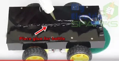
- Glue the bottle
Now, let’s glue the components appropriately on the Home cleaning robot. You can follow the figure to see where each component should go. Make sure you use a strong adhesive so that they stay in place securely.
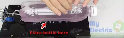
- place the water bottle
Place a water bottle or any detergent bottle in the designated area on the Home cleaning robot to clean the floor. Make sure it is securely fastened so that it does not fall off during cleaning.
- Working condition
To make the Home cleaning robot functional, you need to prepare it for cleaning the floor. For this purpose, take a water bottle or any other detergent bottle and pin a hole in it. After that, take a medical tube and attach it to the bottle’s nozzle. This will allow the cleaning solution to flow out of the bottle when needed.
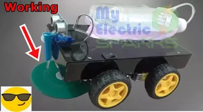
Now, place the bottle on the Home cleaning robot to be easily accessed during operation. You can fix the bottle using a glue gun or any other adhesive. Once you have set the bottle, you can use the Home cleaning robot to clean your floors.
It’s important to note that before using the robot, you should thoroughly examine it to ensure that all the connections are secure and the components are correctly fixed. This will help prevent accidents or damage to the robot while it operates.
Download the Arduino Code
To program the home cleaning robot, you need to download the Arduino Code. You can get the code from the given link Arduino code + configuration. It’s a set of instructions that the robot will follow to perform its tasks. Make sure you download the correct code and save it to your computer.


I’m extremely impressed with your writing skills and also with the layout on your
blog. Is this a paid theme or did you modify it yourself?
Anyway keep up the excellent quality writing, it is rare to see a great blog like this one
these days.
it is self modified
Hi mam ,how are you ? There is problem in coding during downtime. This file is not supported error? Can you help me
what type of error you get?