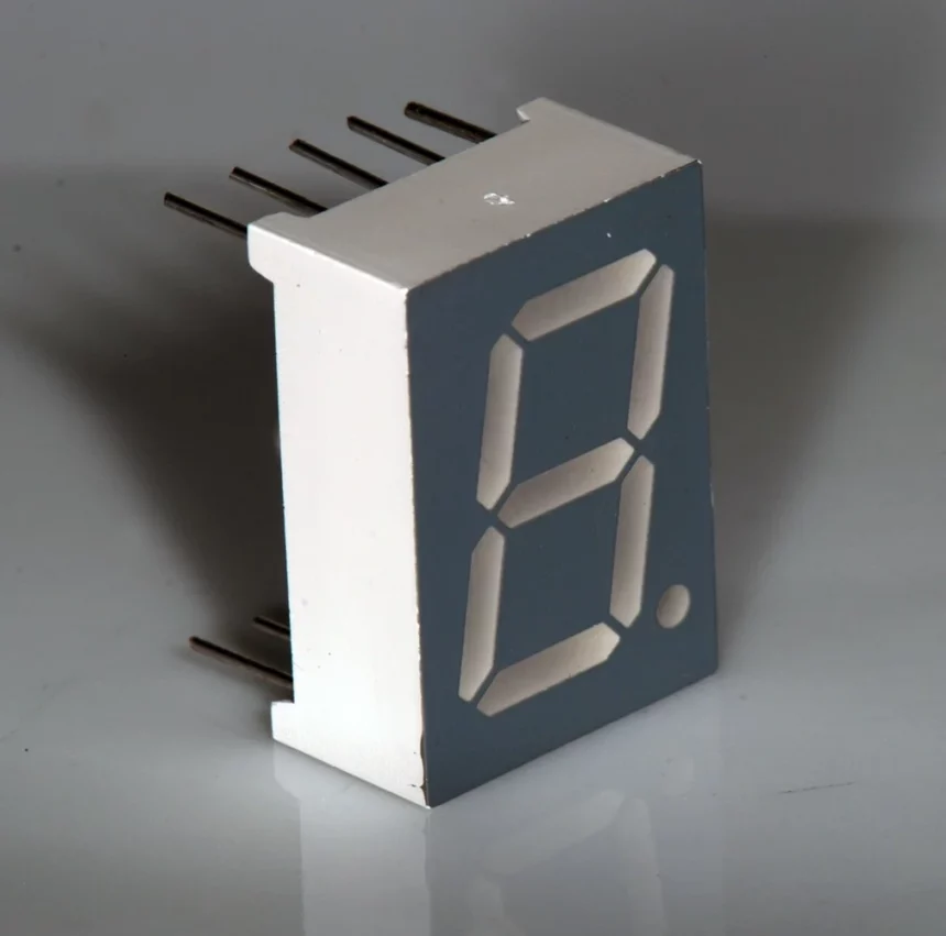
Seven segments display can be described as a type of electronic display device for displaying Numerical decimal numbers. This is an alternative to the more complicated dot matrix displays.
Seven-segment displays are used extensively in digital watches, electronic meters, basic calculators, and other electronic devices that display numerical data.
This seven-segment display can display binary information in decimal format. This versatile technology is used in many applications, including microwave ovens, calculators, washing machines, radios, digital clocks, radios, and other electronic devices.
If You want to study about Light Emitting Diode Visit Our Lattest Topic.
The seven segments are either made of LEDs (Light-emitting Diode) or
LCDs. P-N junction light-emitting diode, also known as LED, emits energy in the form of light. This is in contrast to normal P-N Junction diodes, which emit heat.
Liquid crystal displays, or LCDs (liquid crystal displays), display liquid crystals. The light from an LCD does not directly emit. These LCDs, or LED’s, are used to display the alphabet or numeral. We can display one seven-segment or multiple segments in the order we require.

History of seven Segment Display
F. W. Wood invents seven segments display in the year 1908, as seen in the Patents. The number four was displayed using a diagonal bar. The idea was later rediscovered, and the display system was made. Incandescent bulbs These were used in power plant boiler room signal panels from 1910. Seven Segment Display was first made in 1970.LEDs.
Patents that include seven-segment representations of figures date back to 1903. Patent 1,126 641, when Carl Kinsley invented a method for telegraphically transmitting numbers and letters to be printed on tape in a segmented form. F. W. Wood invents an 8-segment display that displays the Display Filament Seven-Segment

Seven-segment displays were first made with incandescent filaments and an evacuated bulb. Minions are segment displays of filament housed inside DIP packages, similar to modern LED segment displays. They can have as many as 16 segments.Some segment displays used smaller incandescent light bulbs or LEDs instead. These displays worked in a similar way to modern LED segment displays.
In the 1970s, vacuum fluorescent displays were also available.
Early LED seven-segment display had each digit built using a single. The digits were very small because of this. To make the digits easier to read, some added magnifying lenses to the design.
The seven-segment design is often used in posters and tags. Here, the user can either apply colour to preprinted segments or colour through a seven-digit template to create figures such as telephone numbers or product prices.
Dot-matrix LCDs are now more common than LED displays for many applications. However, even with LCDs, seven-segment displays are still very common. The shapes of elements in an LED panel are not fixed, unlike LEDs. They are created on the LCD using photolithography. The shapes of LED segments are more simple rectangles than those of 7-segment displays. Seven-segment LCD screens are very popular on basic calculators due to their high recognition and high visual contrasts compared to dot matrix digits.
Typographers have created more legible typefaces than the seven-segment display, such as New Alphabet and “DB LCD Temp”, and “ION B”.
Seven-segment displays, which use a limited range of letters that look like (upside down) digits, are used commonly by schoolchildren to form words and phrases using a technique called ” calculator spelling“.
Seven Segment Display PinConfiguration
In general, seven-segment displays can be purchased in a ten-pin package. For example, in the above image, you can see the pin diagram for seven-segment displays. A seven-segment display is an electronic circuit that consists of 10 pins.
Eight of the ten pins are LED pins, and these can be left as is. Common pins are located in the middle of the pins. These pins are internally shorted. Depending on whether the common pin is anode or cathode, seven-segment displays can be called common cathode (or common anode), respectively.
They are available from various vendors.

| Pin Number | Pin Name | Description |
| 1 | e | Controls the left-bottom LED of the 7 segment display |
| 2 | d | Controls the lowest LED in the 7-segment display |
| 3 | Com | Based on the type of display, connected to ground/Vcc |
| 4 | c | Controls the right-bottom LED of the 7 segment display |
| 5 | DP | Controls the decimal-point LED of the 7 segment display |
| 6 | b | Controls the top-right LED of the 7 segment display |
| 7 | A | Controls the topmost LED in the 7-segment display |
| 8 | Com | Based on the type of display, connected to ground/Vcc |
| 9 | F | Controls the top-left LED of the 7 segment display |
| 10 | g | Controls the middle LED in the 7-segment display |
Seven Segment Display pinout
Seven different illuminating segments make up a 7-segment display. They are displayed in different combinations to form numbers or characters. These seven segments display binary information. The light-emitting diode is a P-N junction dime that emits energy in the form of light. This differs from the normal P-N junction dime, which emits heat.LCD information using liquid crystal properties and doesn’t emit light directly. These LCDs or LEDs can be used to display the alphabet or numerals.

Top And Bottom View of Seven Segment Display
The top view shows eight segments (7 display segments and one decimal point). This numeral is ‘8’.

The top view shows eight segments (7 display segments and one decimal point). This numeral is ‘8’.
The 7 LED segments, also known as segments, are identified with an alphabet from A through G. Forward biasing. A component or LED will produce light energy that illuminates a portion of the numeral. Another segment, H, is used to display dots.
For representing the decimal point of a number, the dot or decimal point is used. To display 2.5, for example, the dot is used.

Generally, an LED package consists of either all the segments’ cathodes or all their anodes. Thus, each seven-segment display will contain seven pins for displaying the numbers, one joint pin for decimal/dot points, and another pin to show them.
Below is a bottom view of the seven segments. Below is a bottom view showing ten segments. These pins are the anode and cathode pins for the LEDs in the segment. These pins are used to illuminate seven segments.

Internal structure of Seven Segment Display
The display’s internal structure is highly complex. SMD LEDs will be used internally. The show can be broken down into two parts: The internal circuit and the display. The rectangular-shaped LEDs will be used in the internal circuit. To protect them, these two components are enclosed by glass, ceramics, and plastic.
suggested article How to Write Data to RFID Card using RC522 RFID and Arduino
Implementations of seven-segment display
A liquid crystal display (LCD), light-emitting diode(LED) for each segment, and an electrochromic display are possible. Other light-generating or controlling techniques include vacuum fluorescent (VFD), cold cathode gas discharge (Panaplex), incandescent filaments, Numitron, and other light-generating or control procedures. Vane displays, which are electromagnetically flipped light-reflecting segments (or “vanes”), are still used for large signs such as gasoline price totems. The cold-cathode and neon-lamp-like nixie tube was a precursor to the seven-segment display. RCA began selling a display device called the Numitron in 1970.

It used incandescent filaments arranged in a seven-segment arrangement
A multiplexed 4-digit display with seven-segment segments and only 12 pins
A simple LED package typically has all the cathodes (negative terminals) and all the anodes of the segment LEDs connected to a standard pin. Commercial products may have more pins and spaces for pins to go to match standard IC sockets. There are also integrated displays, which can have single or multiple numbers. Some integrated collections have their decoder, but most don’t. Each LED is connected to a pin as described.
Multiple-digit LED displays such as those used in pocket calculators, or similar devices used the multiplexed displays to reduce I/O pins. To illustrate, the anodes for the A segments in each digit position would all be connected to a driver circuit pin. The cathodes for all components would also be connected. The controlling integrated circuit would then turn on the anode drivers and cathodes for each digit. After a brief blanking interval, the following number would get selected and lit in a sequence. This would make it possible to have an eight-digit display with seven segments, a decimal point, and only eight cathode and eight anode driver drivers. Again, after a short blanking interval, the next digit would be selected, and new segments lit sequentially. However, pressing multiple keys simultaneously would result in strange results on the multiplexed display.
X-Ray of a 7-segment multiplexed 8-digit LED display taken from a 1970s calculator
While all the digits on an LED display look light to the naked eye, one number can be burned in multiplexed displays at a time. This is because the flashing of an integer is so rapid that the human eye can’t see it (on older devices, it might be visible to peripheral vision).

Seven Segment Display Working Principle
LEDs can be grouped to create a seven-segment display. Below is a Fig. The front of the seven-segment display is shown in Fig. It has seven LEDs (A-B, C, D and E, F, G), arranged in figure 8. Each segment is a LED. Forward biasing an LED will cause it to light up and produce a bar of light. It is possible to display any number between 0 and 9. By forward biasing seven LEDs in different combinations, you can achieve this effect. Forward biasing seven LEDs allows you to display any number from 0 to 9. For example, the display will show the number 3 if the LEDs A, B, C, D, E, F, and G are lit. The exhibition will also show the number 6 if the LEDs A, B, C, D, and E are lit (forward biasing them). To display the number 0, all segments other than G must be burned.


The schematic diagram for a seven-segment display is shown in the Below Fig. To limit currents to safe levels, external series resistors have been included. The anodes of each of the seven LEDs are connected to a common positive voltage source, +5 V. This arrangement has been called common-anode. We ground point A in Figure. This allows us to light one individual LED, A. This forward biases LED A, which will be lit.

Seven Segment Display Animation

Suggested the article; What is Relay and How it Works?
Types of Seven Segment Displays
Common cathode and common anode are the two types of 7-segment LED displays. The main difference between these two displays is that the common cathode connects all 7-segment cathodes, while the common anode connects all 7-segment anodes. Below is an example of a common anode segment seven.

Common Anode Seven Segment Display
Power must be applied externally at the anode connector common to all segments when working with the CA seven-segment display. Using the ground to the segment’s connection (a-g) will turn on the segment. An additional resistor must also be added to the circuit to limit current flow through each segment of LEDs.

The truth table provides the necessary information to drive the segment of common anode seven.

To display zero on this segment, one must enable logic high on segments a,b,c,d,e, and f and logic low for segment ‘g.’ The following table contains data for seven segments that display numerals starting at 0-9s.
Common Cathode Seven Segment Display
Common cathode seven segments are different than standard anode segments in that all the LEDs’ cathodes are connected. To use this segment, the common cathode must be grounded. The appropriate segment must then be illuminated by power.

TruthTable; Below is the truth table for seven segments

7-Segment Display Segments for all Numbers.
For a display with seven segments, we can create a truth table that lists the segments that must be illuminated to get the decimal digits from 0 to 9.

seven-segment configuration chart
seven-segment Display Truth Table
| Decimal Digit | Individual Segments Illuminated | ||||||
| a | b | c | d | e | f | g | |
| 0 | × | × | × | × | × | × | |
| 1 | × | × | |||||
| 2 | × | × | × | × | × | ||
| 3 | × | × | × | × | × | ||
| 4 | × | × | × | × | |||
| 5 | × | × | × | × | × | ||
| 6 | × | × | × | × | × | × | |
| 7 | × | × | × | ||||
| 8 | × | × | × | × | × | × | × |
| 9 | × | × | × | × | × | ||
Driving a seven-segment Display
A 7-segment display is considered one display but it still contains seven individual LEDs in a single package. As such, LEDs must be protected from over-current. LEDs emit light when they are forward biased. The amount of light that is emitted depends on the forward current. The LED’s light intensity will increase in a linear fashion with increasing current. To prevent LED segment damage, the forward current must be limited and controlled by an external resistor. A red LED segment’s forward voltage drop is approximately 2-to-2.2V. (Blue and white LEDs can reach 3.6V.) To ensure that the segments are properly illuminated, they should be connected with a voltage source greater than this forward voltage value. For a 7-segment red-colored display, each segment of an LED can draw approximately 15 mA to be illuminated correctly. So on a 5V digital logic circuit, the value for the current limiting resistance would be 200O (5v-2v)/15mA or 220O at the closest preferred value. The circuit below explains how the segments of the display connect to a 220O current-limiting resistor.Using resistor for Driving a 7-segment Display
 The switches are used to illuminate the segments of the common anode display. When switch a is closed current will flow through the “a” segment of the LED to reach the current limit resistor connected at pin a and 0 volts. This completes the circuit. The only segment will then be lit. To activate the LED segments of this common anode display, you must switch to ground and set it to LOW.
Let’s say we want the decimal numeral “4” to be illuminated on the display. To light, the LED segments, switches b,c,f, and g would need to be closed. Switches a, B, and C would also be closed for decimal numbers “7”. However, it is difficult to illuminate 7-segment displays with individual switches.
Displays with 7 SegmentsUsually, they are driven by a special type integrated circuit (IC), also known as a 7 segment decoder/driver such as the CMOS 4511. The 7-segment driver is also known as a Binary Coded Decimal (BCD to 7 segment display decoder/driver) and is capable of lighting both common anode and common cathode displays. There are also many single and dual display drivers, such as the TTL 7447.
This BCD-to-7 Segment Decoder/Driver accepts a four-bit BCD input labeled A, B, D, and C for the digits in the binary weighting of 1, 2, 4, and 8. It has seven outputs that can pass current through the appropriate segments and display the decimal number of the numeric LED display.
Because they can supply up to 25mA each to drive LED segments directly, the digital outputs of CD4511 are more powerful than CMOS outputs. This allows for different colors of LED displays to be used and driven.
Driving a seven-segment Display using a 4511
 This simple circuit shows that each segment of an LED cathode display is connected to its own anode terminal, which is connected to the 4511 drivers. The cathodes are connected to the ground. Each output current is limited to a safe level by a 1kO resistor. The four switches provide the binary input for the 4511. We can then see that we can control the LED display with just four switches, instead of the eight previously used. Or with a 4-bit binary signal that allows for up to 16 combinations.
Digital equipment is the most popular display with 7 SegmentsThis is used to convert digital signals into a format that can be displayed and understood. These data are often in the form of numbers, symbols, and characters. The required number is produced by the common anode and common-cathode seven-segment displays. They illuminate the segments in different combinations.
Because they are simple to use and understand, LED-based 7-segment displays have become very popular among Electronics hobbyists. 7-segment displays can be driven by a suitable driver/decoder IC, such as the CMOS4511 or TTL 7447 with a 4-bit BCD input. The LED-based 7-segment displays are being replaced by Liquid Crystal Displays (LCDs), which use less current.
IC Seven Segment Driver
Multiple ICs can be used with the display to allow it to work with a limited number of pins. Therefore, the type of display that we use will determine which IC is used. Because CMOS/TTL devices have a maximum operating voltage of 5 volts, the use of IC will be through resistors. The input and output of the IC will both be in binary. One IC can only operate one display. Some ICs come with an additional pin that allows you to create the circuit for multiple 7-segment displays with IC. Always verify the truth tables before using multiple ICs. The input and output signals of IC will always be hardware-based. To add programming to control the 7 segments, programmable boards/devices can be attached. This complete driver example is available:How to Use Seven Segment Displays?
With any type of device or board, 7-segments are easy to use. The input signal to each led is all that is required for the 7-segment. To make the 7-segment secure, you only need a particular circuit and component. Each input pin should have a resistor of 220ohms. Although the resistors can lower the voltage, the 220-ohm value is only applicable to 5V output devices. An increase in voltage will cause an increase in resistors. This diagram shows how the circuit will look.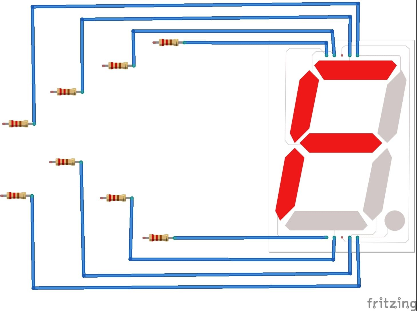 There are two ways to use the LED. One is IC, which takes the 4-inputs. It can generate output data starting at 0-9 and some alphabets on the seven segments.
Seven Segment Display Truth Table
| DECIMAL | INPUTS | ||||||
|---|---|---|---|---|---|---|---|
| a | b | c | d | e | F | g | |
| 0 | 1 | 1 | 1 | 1 | 1 | 1 | 0 |
| 1 | 0 | 1 | 1 | 0 | 0 | 0 | 0 |
| 2 | 1 | 1 | 0 | 1 | 1 | 0 | 1 |
| 3 | 1 | 1 | 1 | 1 | 0 | 0 | 1 |
| 4 | 0 | 1 | 1 | 0 | 0 | 1 | 1 |
| 5 | 1 | 0 | 1 | 1 | 0 | 1 | 1 |
| 6 | 0 | 0 | 1 | 1 | 1 | 1 | 1 |
| 7 | 1 | 1 | 1 | 0 | 0 | 0 | 0 |
| 8 | 1 | 1 | 1 | 1 | 1 | 1 | 1 |
| 9 | 1 | 1 | 1 | 0 | 0 | 1 | 1 |
Seven Segment Display Features
- The 7-segment can be interfaced with nearly every module/device.
- To turn on the LED, it needs 3V. If both low and high are present, the LED will turn on. Sometimes it might even burn.
- Because of its internal structure, the current cannot flow from one side to another.
- One device can display up to 10 decimal digitals.
- Displays can be used to display multiple digits. The display’s number will increase with each use.
Applications of Seven Segment Displays
- Seven segments can be used in digital calculators and electronic meters, digital clocks, and clock radios.
- Because of their low current consumption, LCDs are used in most 7-segment applications today.
- Digital clocks
- Clock radios
- Calculators
- Wristwatches
- Speedometers
- Motor-vehicle odometers
- Radiofrequency indicators
