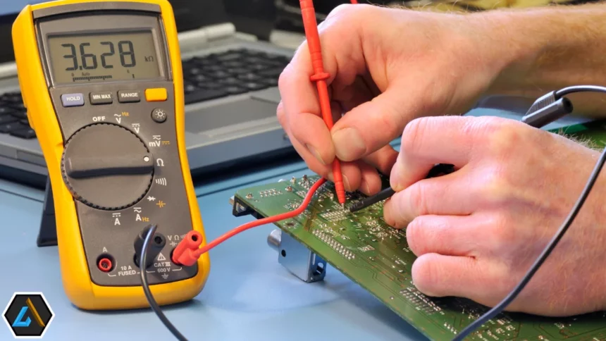
This article is about what a capacitor is, how to test a capacitor, and Where it’s mostly used. How to Discharge a Capacitor? If you read the article with full concentration, you’ll understand all the given topics in this article.
WHAT IS A CAPACITOR?
It’s an electrical or electronic instrument that stores energy as an Electronic charge. It is mostly used in electronic circuit boards and appliances as it performs many functions.
Why do we need to test a capacitor?
It’s the rule of buying; if you buy any appliance tested, it must check whether it is working. Some of the methods for testing capacitors are given below;
1: In an active current flowing circuit, the charge starts to build upon one of the plates inside it when it is placed. Once it starts rejecting more charges, then it means that the capacitor is fully charged.
2: The capacitor discharging can be explained in such a way that when the circuit demands back its charge, just like bypassing it, it releases the chargeback to the circuit and continues until the circuit stops demanding or the charge is completely released.
CLASSIFICATION of capacitor:
It can be divided into 2 types.
Electrolytic and non-electrolytic. Just like other electronic appliances, it can be easily permanently damaged by the voltage signs.
The capacitors that often get damaged and release more current in a minimum period or those that can’t hold current due to overtime are known as electrolytes. On the other hand, a capacitor that leaks all its charge is known as non-electrolytic.
There are numerous methods to check the capacity of capacitors. Some of these methods are listed in this article.
NOTE: Some of the best ways to check a Capacitor are mentioned and we had added it just to show the possibilities and to increase the knowledge of a reader.
How can it be Discharged?
The word discharge means “not having the ability to store current or charge. On the other side, it is an electronic device used to store energy. So now it’s important to understand how properly it can be a Discharge. It’s very important because it is constructed so that if the current is disconnected, it can still hold a current. It can give a person an electric shock if it’s not fully discharged and a person’s hand unconsciously touches the lead; then, it will discharge through the human body.
Using a Screwdriver:
At first, disconnect it from a circuit carefully, and then don’t touch its terminals. Then, take a screwdriver with a long rubber or wooden handle and hold it in one hand, then take the capacitor in the other hand and connect the metal part of the Screwdriver to its terminals.
Then, the electric discharge will take place, and you will hear the crackling and see the current sparks. It shows the electric discharge. Do it a couple more times and ensure it is fully discharged.
Using a Discharge Resistor (Bleeder Resistor)
This one is the safest way of discharging. It’s commonly used in power supplies and circuits where the Bleeder Resistor is parallel to the output. When the current is disconnected, its remaining charge is released through the Resistor.
FOR EXAMPLE:
Make a circuit by putting a large-value resistor (a few kilo Ohms ) with a current rating of up to 5W and then connecting it with the terminals. Use wires with crocodile clips on either side instead of using direct wires. Then, the flow of discharging will slow down or decrease, and the voltage reading on both terminals will be easily noted while using a Multimeter.
For example, considering you have a 1000µF eligible for 50V and want to experiment with discharging to 1V, using a 1KΩ Resistor, it will take almost 4 seconds to discharge the capacitor. Also, the power rating of the Resistor will be at least 2.5W.
NOTE: High Power Supplies Resistors are mostly expensive as compare to normal Resistors of 1/4 Watt or 1/2Watt
Method 1: Checking a Capacitor using a Multimeter with Capacitance Setting
In this method, a Multimeter is used to check the capacity. It’s one of the easiest, fastest, and best methods to check a Capacitor. This method mostly uses a digital multimeter with mid- and high-end Capacitance.
Mostly, Multimeter displays the capacity, but a few Multimeters show other things like ESR, leaking, etc.
STEPS:
- At first, separate it from the circuit and discharge it completely. Note the visible value; usually, its Capacitance is in microfarads.
- Secondly, For measuring capacity, set a knob on the Digital. Now connect the Multimeter probes to the terminals. If polarized, connect the black clip with the negative and the red clips with the positive terminals. To make it easy, there must be a sign on either side. Connect it according to your choice in a non-polarized one, as it doesn’t have polarity.
- In the third step, note the reading of the Digital Multimeter; if the rating is closer to the actual value given on the Capacitor, then it’s considered good.
- Last but not least, if there is a lot of difference between given and noted values, then return it; it is dead.
NOTE :
If you want to measure Capacitor capacity from nano farad to a few hundred microfarads, use this method. The capacitance range in the above-given values can be measured easily.
ALSO READ: How to Interface oled display with Esp32 ?
Method 2: Checking a Capacitor using a Multimeter without a Capacitance Setting
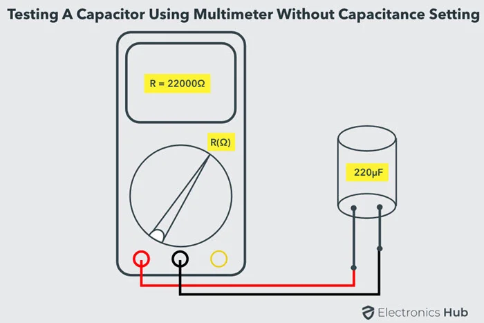
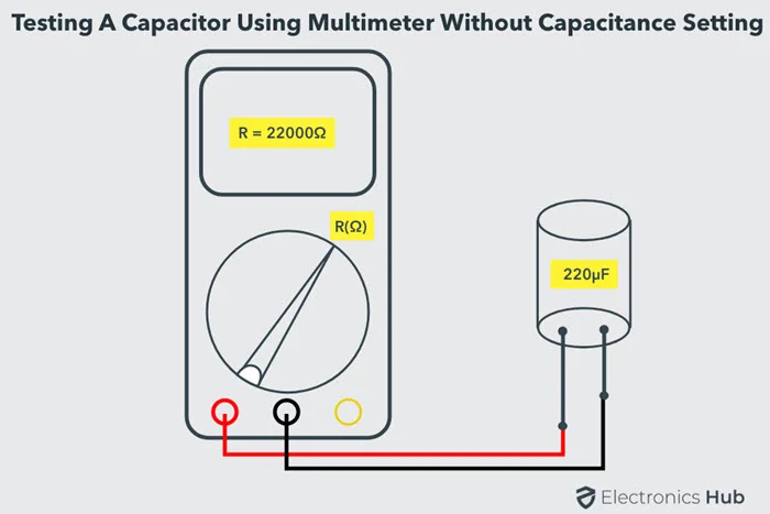
All digital multimeters can check the capacity except those of low and cheap quality, as they don’t have such features, but we can still use them in testing.
Steps:
• The First Step of all methods is removing from the circuit and ensuring it’s fully discharged.
• The Second step includes making a proper setup for measuring the Resistance through a Multimeter, i.e., setting the knobs to the given resistance setting. In the case of multiple ranges of resistance Measurement, always select the higher range one between 20 KΩ to 200 KΩ).
• In the third step, if it is polarized, then connect the black crocodile clip to the negative terminals and the red crocodile clip to the positive terminals.
• In the fourth step, Note down the value of Capacitance that was visible for a short period of time; the Multimeter will display the value of Resistance, and it will also display the Resistance of an open circuit. Then remove it from the Multimeter and repeat it a few times.
Conclusion of steps:
By repeating the process again and again, it must show the same result each time to make it a good Capacitor. No change in the Resistance of further results shows the capacitor is used uselessly or is dead.
This method for checking the Capacitance can’t be correct, but it can separate the good and bad Capacitors.
Method 3 Testing it by measuring the Time Constant:
Another method for checking whether the capacitor is good or bad is measuring the Time Constant Method. This method will work if the value of the Capacitance is given or known. When the capacitor’s given value and actuarial value are similar, the capacitor is the best.
NOTE: In this method, an Oscilloscope should be used instead of a Multimeter because it’s the best one
Here, a question arises: what is the Time Constant?
It is the charging time a Capacitor takes to charge its plates up to 63.2% from the supplied voltage through the known resistor. Capacitance and resistors are necessary for measuring the time constant, and symbols derive its formula. Some of these Symbols are given below;
- For Capacitance (C)
- For Resistor (R)
- For Time Constant, TC or Tau – τ is used.
- Formula is = τ = RC
STEPS:
- First, cut the voltage or power supply to the capacitor, capacitor disconnect it from the circuit, and carefully discharge it.
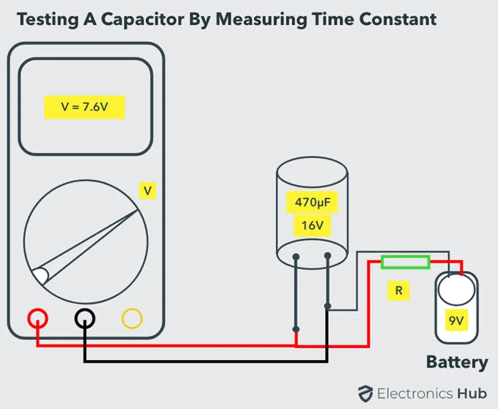
- In the Second Step, Connect the Capacitor with a known resistor whose value is typically 10 KΩ. Then, Allow the power supply carefully with known voltage After completing the circuit.
- In The Third Step, Note the Time the Capacitor charges its plates up to 63.2% from the power supply or supplied voltage, i.e., Charging up to 63.2%, a Capacitor needs up to 7.6V; if the supplied voltage is 12V.
From the above example, it’s clear that the mentioned Time and Resistance measure the Capacitance of a it with the values mentioned on it.
The fourth step is usually the conclusion of the above method. The capacitor is known to be best if the noted value and given values of the Capacitor are nearly matching and if the values are different then Capacitor needs to be exchanged.
By using the above method, the discharging time of a Capacitor can also be calculated. Time should be noted down when the discharging value of a Capacitor reaches 36.8% at peak volts.
ALSO READ: What is Relay and How it Works?
Method 4 Test a Capacitor with a simple Voltmeter.
The capacitor is an electrical device that is constructed in such a way that it can control high voltage. This method uses the voltage rating to check a capacitor’s capability to be named good or bad.
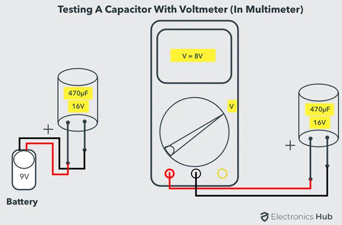
STEPS:
The First Step of each method is to disconnect and discharge a Capacitor for safety purposes.
- In the Second Step, research is conducted on the capacitor’s voltage rating. The maximum voltage Capacity of a Capacitor is 16V, 25V, 50V, etc. The capacitor can easily control given voltage values.
- In the third step, Create a circuit by adding or connecting the battery or power supply, but be careful with the voltage supply as it should be less than the maximum voltage rating .i.e you can add a 9V power supply or battery to the capacitor whose maximum voltage value is 16V.
- If you have a high-power supply, you should construct a voltage value that can be used and must be lower than the capacitor’s mentioned voltage.
- In the Fourth Step, Apply the power supply to the capacitor for a few minutes to get charged and then cut off the supply. Then, start measuring the capacitor voltage by connecting the terminals of the capacitor and voltage by changing the digital multimeter to DC voltage mode.
As a result, the noted voltage value should be similar to the Voltage values on a Capacitor. It makes the capacitor useful, and you can say it’s a good one, but if there is a lot of difference in both ratings or values, it means this capacitor needs to be changed.
Note: When using a Multimeter, the first value should be noted as it will decrease with time, but don’t worry, it’s normal.
Method 5 Testing a capacitor using an Analog Multimeter (AVO Meter)
Before moving forward with this method, we should know what an Analog Multimeter (AVO Meter) is.
Answer: An electrical device that measures different quantities in a circuit, like a digital multimeter. For example, Current (A), Voltage (V), and Resistance (O).In this method, an Analog Multimeter is used for testing Capacitor Capacitance by using its ohmmeter.
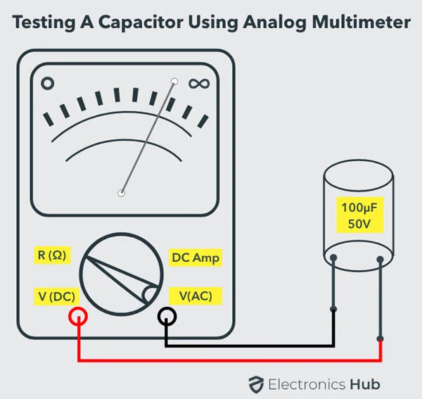
Steps :
- As always, the First Step is to disconnect and discharge a Capacitor. They’re also easy to discharge a Capacitor using a high-wattage Resistor or an LED.
- In the Second Step, select a higher range position if multiple ranges exist and fix the device in the ohmmeter position. Then, connect the capacitor to the Multimeter probes and note its reading.
- As a result, the capacitor is good if its resistance value goes from lower to higher, and if its value remains lower all the time, it is a capacitor that needs to be changed.
- There’s also an exceptional case when the Capacitor value remains higher all the time, which means it’s an open Capacitor.
- In this method, both hole and surface mount Capacitors can be used.
ALSO READ: Different Types and Applications of Amplifiers
Method 6 Shorting the Leads of a Capacitor (Traditional Method – only for Professionals)
This method is mentioned at the end of the article as it’s one of the dangerous ways of testing a Capacitor. Professionals should only use it if the result of the other methods doesn’t satisfy a person’s mentality.
PRECAUTIONS: Testing capacitors using this method poses a significant risk of electrical shock and explosion. Use only as a final option and strictly by qualified personnel with proper safety equipment.
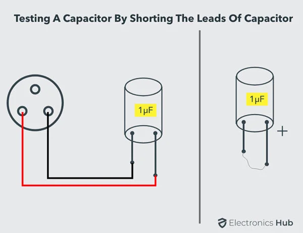
STEPS:
- As Usual, First, the power supply should be cut down, and the capacitor should be discharged completely.
- In the Second Step, connect the Capacitor terminals to the Power supply. Noted that only Non-polarized Capacitor should be used with Capacitance of 230V AC. In the case of 24V DC, any Capacitor can be, but the proper setup is needed for polarized Capacitors.
- In the Third Step, allow the power supply to the capacitor for a few seconds, then switch it off. Even disconnect the terminals of a capacitor from the power supply.
- Now, discharge the terminals using a metal contact. Also, be careful and insulate yourself properly.
- As a result, the current sparks from a Capacitor’s terminals show its condition. The larger and stronger spark means it’s good, and the smaller and weaker sparks mean it’s bad and needs to be exchanged.
- This method can only separate the weak capacitor from the capacitor and shows the capability of holding a charge within the capacitor.
Conclusion
After reading the article with full attention, you’ll now understand what a capacitor is and how it’s tested using different methods. This article has also mentioned testing methods for beginners. Comments below what you think about the article and if you have any problems or questions.

