
In this article, you will learn how to Interface PCF8574 I2C LCD with ESP8266 NODEMCU motherboard. You will also learn about the PCF8574 I2C LCD working method and coding system here.
Before proceeding, you must know about PCF8574 I2C LCD Module and LCD Display. Here a question arises what is PCF8574 LCD? So the answer is that the PCF8574 I2C LCD is a uniquely designed module with lengths of 16×2 and 20×4 LCD Display, with different readings.
Need for I2C LCD
Let’s know a little bit about ESP8266 nodemcu. It is the best motherboard ever developed for the Internet or online applications. The main thing in this pin is the GPIO Pins. For SPI Flash IC and UART, all the GPIO-related pins are removed, and 9 GPIO pins can be used for free.
But in this DIY project ESP8266, NodeMCU uses 6 GPIO pins. Even if the communication mode is in a 4-bit parallel way. The distribution of the 6 GPIO pins is explained as four pins are used for Data, one for RS and one for E.
Note: If you plan to use other essential sensors and devices for this project, then the number of GPIO pins must be reduced, as using that many plugs for the LCD is impossible.
You can also refer to the below article. How to Interface OLED display with Esp32?
After using other sensors, the I2C LCD Module can be fully utilised, as its uniquely designed LCD Display and communication process occur through the I2C interface. As a result, instead of 6 GPIO Pins, two pins are used, named SDA and SCL of I²C.
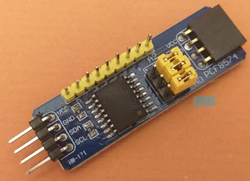
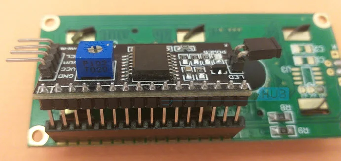
A Brief Look at PCF8574 I2C LCD Module
As the article clearly shows the headline of today’s DIY project, you should know that the PCF8574 I2C LCD Module is designed based on PCF8574 GPIO Expander IC. The expander is used to expand a microcontroller and controls its communication with it through the I2C interface.

Another characteristic of the I2C LCD Module is to show the result of the experiment on the LCD or to drive the characters on LCD. It also has a connection or designed potentiometer for contrast management and a jumper for controlling Backlights.
ESP8266 NodeMCU I2C LCD
Let’s get started with the actual DIY project working method. If you have read our other articles, you must know that ESP8266 NodeMCU pins D1 and D2 are GPIO 5 and GPIO 4. These pins are mainly used for I²C communication purposes.
ABOUT PINS: D1 or GPIO 5 = SCL Pin D2 or GPIO 4 = 0SDA Pin
Both these pins are used to connect with the PCF8574 I2C LCD Module. For connecting purposes, LCD should be plugged into these pins and supply power for display purposes.
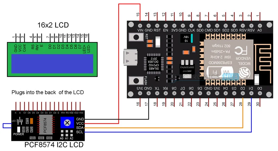
The diagram shows the connections between the I2C LCD Module and ESP8266 NodeMCU.
| I2C LCD Module | ESP8266 NodeMCU |
| GND | GND |
| VCC | VIN |
| SDA | D2 – GPIO 4 |
| SCL | D1 – GPIO 5 |
Note: The LCD needs a power supply between 4.7 V to 5.3 V; PCF8574 IC requires a power supply is 2.5 V to 6V; from NodeMCU, 5V power is supplied instead of 3.3V.
Components Required
- ESP8266 NodeMCU
- PCF8574 I2C
- LCD Module 16×2
- Character LCD Display
- Breadboard
- Connecting Wires
Circuit Diagram
The given image shows ESP8266 NodeMCU I2C LCD Interface.
Preparing Arduino IDE
To complete this DIY project, you need to know some of these Preparing steps to avoid errors and to give perfection and if you have never used the I2C LCD Module before, then follow the steps.
- STEP 1: Open Arduino IDE
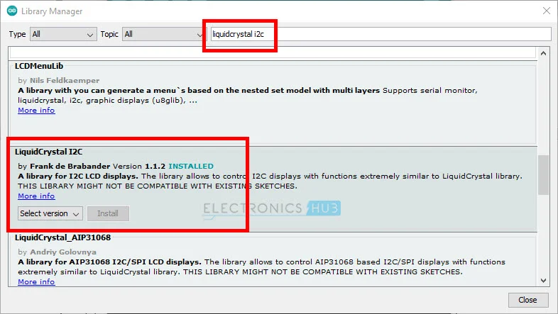
- STEP 2: Click on Tools -> then go to manage libraries.
- STEP 3: In the search bar, type ” LiquidCrystal_I2C ” library by Frank de Brabander.
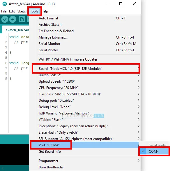
STEP 4: As previously instructed, establish all the required connections and connect the ESP8266 NodeMCU to your computer. Ensure you’ve chosen NodeMCU from the available boards and accurately configured the appropriate COM Port.
Getting the Slave Address of the I2C LCD Module
Before going ahead, let me tell you that the slave address is the most essential code for displaying on LCD. If you are an expert, you must know that the primary basis of I2C communication is that a master has to communicate with an enslaved person only if the slave’s address is known.
In this DIY project, the ESP8266 NodeMCU is the master, and the PCF8574 I2C LCD Module is the slave.
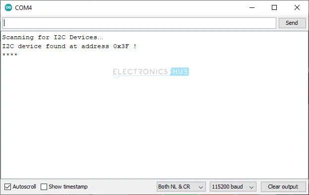
So, use the given code to get the slave address of the LCD Module. After completing all the necessary setup, add the code to Interface PCF8574 I2C LCD with ESP8266 NodeMCU and open the Serial Monitor.
Code
Here is the code text
#include <Wire.h>

void setup()
{
  Wire.begin();
  Serial.begin(115200);
  while (!Serial);
}

void loop()
{
  byte error, address;
  int I2CDevices;

  Serial.println("Scanning for I2C Devices…");

  I2CDevices = 0;
  for (address = 1; address < 127; address++ )
  {
    Wire.beginTransmission(address);
    error = Wire.endTransmission();

    if (error == 0)
    {
      Serial.print("I2C device found at address 0x");
      if (address < 16)
      {
        Serial.print("0");
      }
      Serial.print(address, HEX);
      Serial.println(" !");

      I2CDevices++;
    }
    else if (error == 4)
    {
      Serial.print("Unknown error at address 0x");
      if (address < 16)
      {
        Serial.print("0");
      }
      Serial.println(address, HEX);
    }
  }
  if (I2CDevices == 0)
  {
    Serial.println("No I2C devices found\n");
  }
  else
  {
    Serial.println("****\n");
  }
  delay(5000);
}
view rawESP8266-I2C-LCD-Demo.ino by GitHub
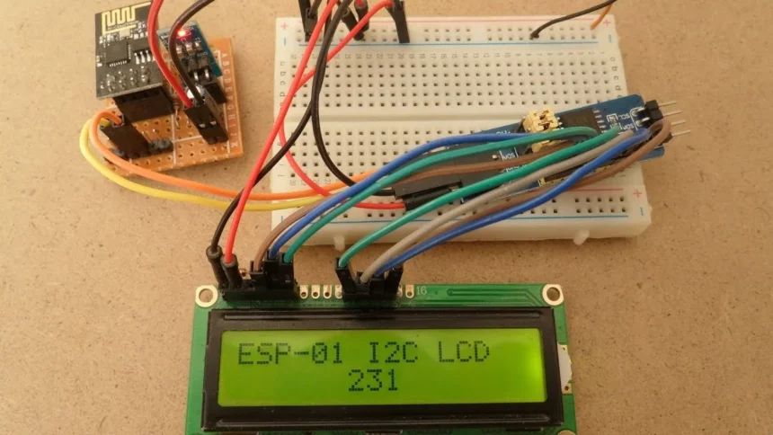
ESP8266 will look for any slaves, and if a slave is acknowledged the system works by detecting or searching for any slave, and when its slave is acknowledged, the ESP8266 will scan its address and print it on the serial Monitor. From the image, you can see that the slave address is 0×3F in my case. This code is used as the main code.
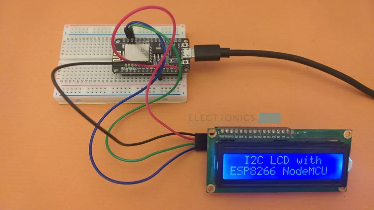
Displaying Simple Text
While further moving ahead with the step-wise process, let’s see how simple text is displayed on a 16×2 LCD. No extra connections are needed.
Code
#include <Wire.h>
#include <LiquidCrystal_I2C.h>

LiquidCrystal_I2C lcd(0x3F, 16, 2);

void setup()
{
  lcd.init();
  lcd.backlight();
  lcd.setCursor(0,0);
  lcd.print("  I2C LCD with ");
  lcd.setCursor(0,1);
  lcd.print("ESP8266 NodeMCU");

}


void loop()
{

}
ESP8266-I2C-LCD-Demo.ino by GitHub
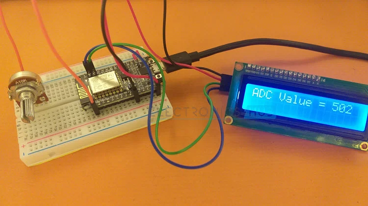
ADC Value on LCD
In this project, the small circuit is also created by joining a 10 KΩ Potentiometer to the ADC pin of NodeMCU and shows the result of ADC on LCD using the I2C LCD Module.
As the ESP8266 has specified quality as its ADC has a revolution of 10-bit, its output range will relay between 0 to 1023.
NOTE: you should know that ESP8266 had only ADC Channel, as on NodeMCU Board, A0 is the number of ADC Pin. The 10 KΩ Potentiometer of the wiper pin is attached with A0 of NodeMCU, and at the same time, the other two pins of the potentiometer are connected to 3.3V and GND.
Warning: POT can only Tolerate voltage up to 3.3V, so be careful connecting POT with ESP8266 ADC.
Circuit Diagram
The images below show the connections of the Potentiometer to ESP8266 NodeMCU and display the ADC result on the I2C LCD.
Code
#include <Wire.h>
#include <LiquidCrystal_I2C.h>

#define analogPin A0 /* ESP8266 Analog Pin ADC0 = A0 */
int adcValue = 0;  /* Variable to store Output of ADC */

LiquidCrystal_I2C lcd(0x3F, 16, 2);

void setup()
{
  lcd.init();
  lcd.backlight();
  lcd.setCursor(0,0);
  lcd.print("ADC Value =      ");

}


void loop()
{
  adcValue = analogRead(analogPin); /* Read the Analog Input value */
  lcd.setCursor(0,0);
  lcd.print("ADC Value =      ");
  lcd.setCursor(12, 0);
  lcd.print(adcValue);
  delay(1000);
}
ESP8266-I2C-LCD-ADC.ino by GitHub
Conclusion
After reading this article with full attention and following the step, you might have a complete project now. You did a great job going through this complex process; now, things might be easy for you, and you have also learnt the uses and importance of Interface PCF8574 I2C LCD with ESP8266 NodeMCU, and it works.
For any difficulty, comment down below or contact us through email. Thank you ❤️