This Article is based on all the topics related to Autotransformer. On the other hand, this Article is a complete guide about Autotransformer construction, working principles, Symbols, using techniques and precautions, etc. You must read it carefully to everything to be precise.
As we know that it’s a modern age, and many technologies are invented every year, so Autotransformer is the category of electronic appliances. It’s further added to subdivided types known as Electromagnetic appliances. As mentioned, this Article is based on Autotransformer, so for better understanding, let’s first understand what auto-transformers are and how it works.
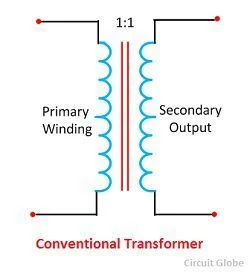
CONVENTIONAL TRANSFORMER DEFINITION:
Autotransformer is electrical appliances sub-categorized into Electromagnetic devices whose working principles are based on mutual induction for transferring data from one circuit to another.
MUTUAL INDUCTANCE:
This process takes place in Electromagnetic appliances. Its working principles are based on magnetic fields. When the magnetic field combines two or more Inductance, it’s known as Mutual Inductance.
EXAMPLE:
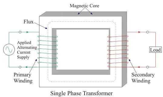
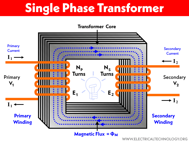
SINGLE-PHASE TRANSFORMER:
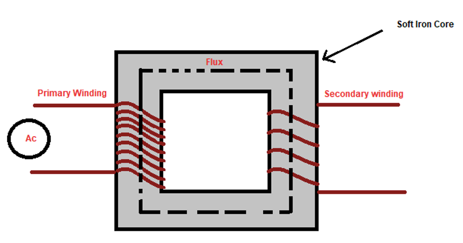
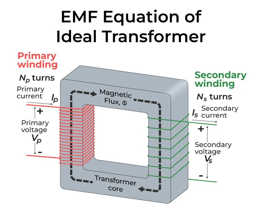
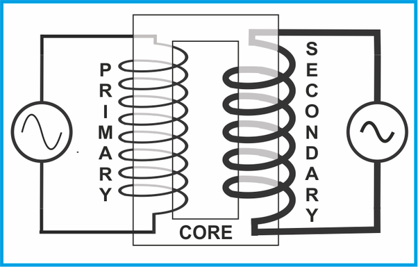
This type of transformer is an example of mutual induction as its working principles are based on 2- coils known as Primary and Secondary coils.
WORKING:
When power is supplied, it’s received by the Primary coil, producing a magnetic field. After that, the primary coil magnetic field is combined or Induced into the secondary coil. The secondary coil will connect to the load and supply the current correctly.
TYPES:
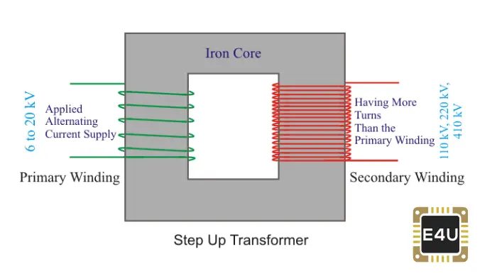
If the Transformer is constructed for increasing voltage to a high level, it’s known as a “Step up transformer.”
In the same way, If the Transformer is designed for
Decreasing the voltage ⚡ to a low level is known as a “Step down transformer.”
What is an Autotransformer?
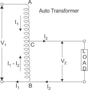
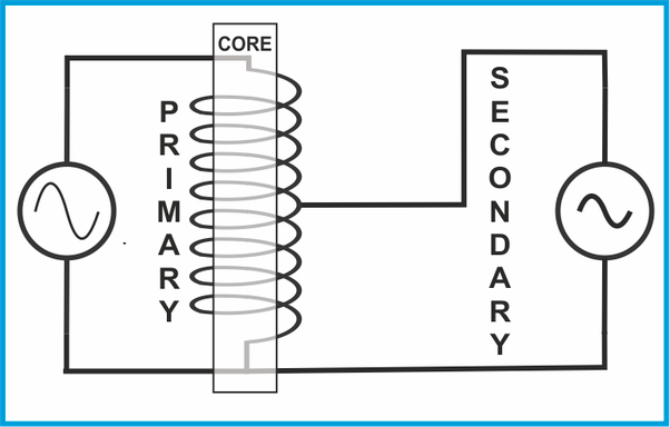
An autotransformer is an Electromagnetic device in which one winding is common to both primary and secondary coils.
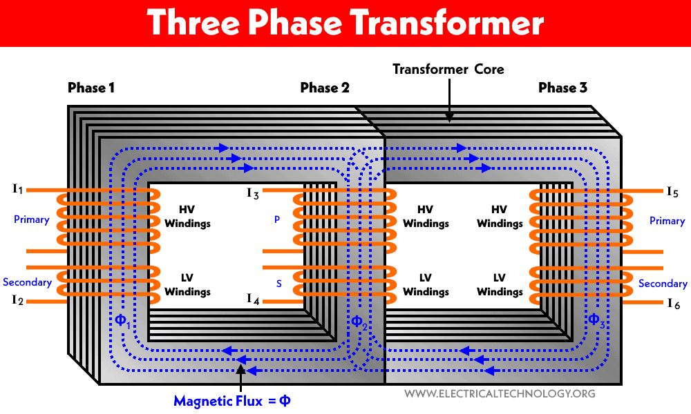
From the above discussions, we concluded that an ordinary transformer has two separate physical Windings, which are then attached by the magnetic field, and the magnetic core produces this field.
At first, the primary winding separately receives the power from the supplied source, and the Secondary winding transfers the current to the output load.
But in Autotransformer’s case, only one winding is used as both primary and secondary coils. And the word ” Auto” here means that the supplied voltage ⚡ will be automatically controlled (either increased or decreased according to the need).
Autotransformer is commonly added to those electronic appliances which don’t requires electrical isolation between input and output. Some of the popular uses are Industrial and marine appliances. (Simple Autotransformer image to be added).
Autotransformer Theory and Design
There are Autotransformers:
1)Step up
2) Step down and
3) Variable Autotransformer
As we know, supplied current transfers occur by induction, and the provided to the load is by conduction.
VARIABLE AUTO-TRANSFORMER:
This type of Autotransformer is primarily found in laboratories and industries as it produces an AC voltage in an extensive range only from a single source. The description of the above image is given below:
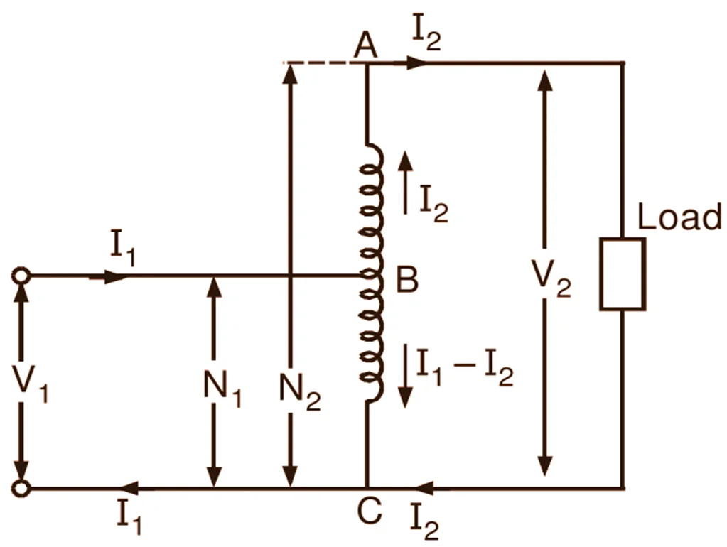
The above image shows the types of autotransformers. IN PART A of the above image, the first and second winding are attached, and the transformer’s turn ratio mentions the voltage value in the first and second winding.
IN PART B: Part B is explained differently in the diagram above. The first winding is named Common winding because its working principles are different, and the other is called series winding because it’s attached to it in series form.
The role of voltage in Autotransformers in the above image (a) is given by:
V₂= Vc + Vse
But,
Vc / Vse = Nc / Nse
===> V₂ = Vc + (Nc /Nse) * Vc
But,
V₁ = Vc
===> V₂ = V₁ + (Nc /Nse) * V1 = ((Nc +Nse)/ Nse) * V₁
The current value on each side of the Autotransformer is shown in the above image (a) is given by:
I₁ =Ic + Ise
But,
Ic = (Nse/Nc) * Ise
===> I₁ = Ise + (Nse/Nc) * Ise
But,
I₂ = Ise
===> I₁ = I₂ * (1 + (Nse/Nc))
Note: The Amazing fact about Autotransformer is that not all Autotransformer uses winding for transferring current. But if a conventional transformer is used in place of an Autotransformer, it can control more power than the original one.
The Autotransformer input apparent power is given by:
Sin = V₁I₁
and the output apparent power is given by,
Sout = V₂I₂.
It’sit’s easy to show both input and output apparent power e through equational.
Sin = Sout =SIO
In the equations, SIO shows the input and output apparent power and Their relation with the current supply of primary and exact windings can be derived from the following:
Sw =VcIc = VSE * ISE
Sw =V₁ * (I₁-I₂)
Sw =V₁I₁ – V₁ I₂
Sw = SIO * Nse / (Nse + Nc)
For example, suppose:
An autotransformer of 500 Kva value is attached to 110 Kv to 138 Kv line, so Nc/Nse value ratio will be 110/28. After using the derived formula of winding and apparent power, the actual power values can be calculated to see the speed of energy that has traveled through the windings.
Sw = Sio x Nse / (Nse + Nc)
Sw = (5000) x 28/ (28+110) = 1015 KVA
1015 KVA is the value of actual winding power, but the Autotransformer can control up to 5000 KVA. This means an autotransformer can handle five times more power, and its capability is five times smaller than a conventional two-winding transformer.
Now for controlling 1015kva current value, a special copper wire is designed. If the supplied voltage is 220, then the apparent current will be
Apparent Current = 1015 Kva/220 = 1015 x 1000/220= 4613.63 A.
Copper wire should be chosen from SWG or AWG wire gauge table for accurate, current density.
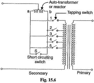
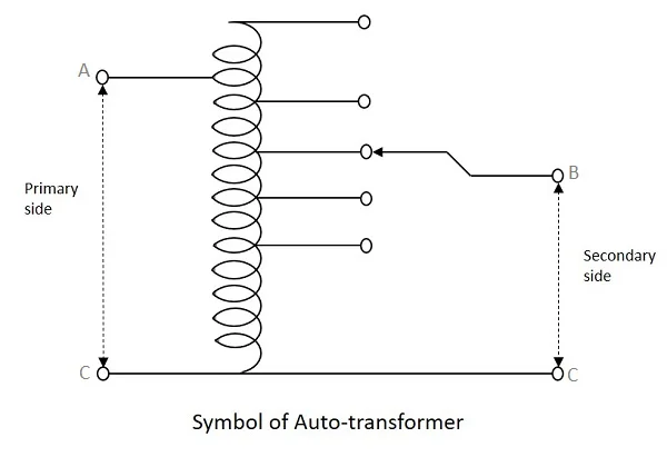
It can also be designed with more than one single tapping point. Auto-transformers are also used to give out different voltage values along its winding.
Auto-transformer with Multiple Tapping Points
The following table is given to briefly explain the different types of auto transformers based on their connection:
Symbols of Auto-transformer
1-Phase Auto-transformer symbol
3-Phase Auto-transformer symbol
Types of Autotransformers
There are three general types of auto transformers categorized based on the use of autotransformer:
- Step Up Autotransformer
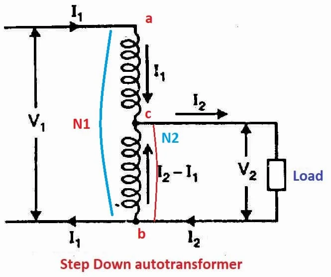
- Step Down Autotransformer
- Variable Auto transformer
Step Up Auto-transformer
The type of Autotransformer working principle is based on increasing the value of the voltage to the required value. The output of voltage depends on the turn ratio of the Autotransformer.
As we had already studied that each loop of a inductor is considered as battery. If there are more loops in the output circuit then it means that more AC voltage is produced compared to input. As mentioned above when output and input applied power is equal then for maintaining purpose power value will be decreased.
Step Down Auto transformer
The build up of both autotransformer is same but their are slightly difference in their primary and secondary voltage supply as Primary voltage value is high and secondary voltage value is low. Because of this it’s known as Step down transformer.
Variable Autotransformer ( Variac or Dimmer Set)
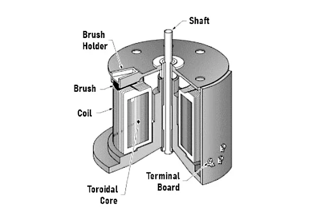
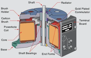
This type of Autotransformer is primarily used in many appliances, but the changing output voltage Capacity is needed in a few cases. This autotransformer type is easy to use and very beneficial because it can be fixed in any supply voltage by switching the knob. Also, they can be used instead of step up and step down Autotransformer.
The middle part is known as a knob. The voltage changes while roaming the knob. It can also be designed with many taps and perform as an AC voltage regulator when needed.
This type of Autotransformer can work as an Automatic voltage regulator after adding circuitry sensors. This is also known as Variac or Dimmer Set.
Design of Autotransformer
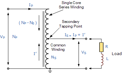
In Autotransformers design, the flow of current is in the opposite direction. If the primary current Ip flow is in the order of a single winding, then the secondary current will be flowing in the opposite. As a result, the winding that creates the secondary voltage Vs., the power value produced will differ in both Ip and Is.
In Autotransformers, more than one tapping point can be constructed to generate different power supplies and, as a result, to produce voltage Vp, as shown in the above image.
Construction Of Auto Transformer
An autotransformer is designed with one copper wire used by both primary and secondary circuits. At least three tapping of laminated silicon steel core come out of a copper wire as the wire is rounded by laminated silicon steel core. Both the primary and secondary have the same neutral point of winding.
The given diagram better explains the construction. In the above chart, Primary terminals are permanently fixed. Thus you can say that magnetically and electrically, primary and secondary windings are attached.
USES AND APPLICATIONS OF AUTOTRANSFORMER:
As we had discussed, what are Autotransformers? Now you might know that it’s a particular power-suppling transformer that uses only one isolated winding to step up or down the power supply.
The word ” Auto” has been derived from Automatic, but here, it doesn’t perform any Action Automatically; instead, the talk shows the performance of the single copper coil that works alone. This type of transformer is best for low voltage ⚡ appliances.
Applications Of An Autotransformer
Autotransformers can be used in given appliances for different purposes; some of these purposes are:
1: It is used in squirrel cage induction motors to supply power up to 50% to 60% of the stator for starting purposes.
2: It’s also used to maintain voltage ⚡ in distributing cable to power up the wires.
3: Autotransformers are mainly and commonly used in Industries, for example, paper mill factories.
4: It is also used in audio systems and railways.
5: In testing laboratories, it’s used by electronic apparatus for testing purposes.
6: It’s also used for increasing voltage to the desired level in AC feeders.
Advantages of Autotransformer
- Losses are decreased for a given KVA capacity.
- Small in size and weight.
- Due to its size, it can be fixed anywhere.
- Voltage is controlled to give out outstanding performance.
- The budget is low.
- For starting low current requirement.
- There is no fixed voltage value. Autotransformer is constructed with a copper metal core which is required in less amount.
- In the conventional transformer step, up and step-down voltage is fixed, while output varies per requirement in the autotransformer.
Disadvantages of Autotransformer
- Neutral is impossible because of the same winding.
- As mentioned above, the Autotransformer works on electrical and magnetic processes, so more isolation is required for safety measures.
- It can’t be used for high voltage works as any disturbance in primary voltage will result in transferring all power supply to the other side. Hence it can’t be used for high power supplies.
Comparison Chart
| Aspect | Auto-transformer | Conventional Transformer |
|---|---|---|
| Definition | One winding, acts as both primary and secondary | Separate primary and secondary windings |
| Number of Windings | One winding on laminated core | Two separate windings |
| Insulation | Primary and secondary not insulated | Primary and secondary insulated |
| Induction | Self Induction | Mutual Induction |
| Size | Small | Large |
| Power Transfer | Partly by transformation and partly by direct connection | Through transformation |
| Voltage Regulation | Better | Good |
| Winding Material | Requires less | Requires more |
| Circuit | Primary and secondary circuits connected magnetically | Primary and secondary circuits connected both electrically and magnetically |
| Connection | Depends on tapping | Connected directly to the load |
| Starting Current | Decreases | Decreases by 1/3 times |
| Excitation Current | Small | Large |
| Economical | More | Less |
| Cost | Less costly | More costly |
| Efficiency | More | Less |
| Leakage Flux/Resistance | Low | High |
| Impedance | Less | High |
| Losses | Low | High |
| Output Voltage | Variable | Constant |
| Applications | Starter in induction motor, voltage regulator, railways, laboratory | Power system step-up and step-down |
The key difference between an Autotransformer and a transformer
- The first difference between these two transformers is that in Autotransformers, there’s only one winding performing as Primary and Secondary coils. In contrast, the transformer has two separate windings for each coil.
- As there is one winding in Autotransformers, its working principles are based on Self-induction, while the transformer is working codes based on mutual inductance because of two separate coils.
- When both transformer sizes are compared, then Autotransformers are smaller than transformers.
- Due to Autotransformer’s small size, it’s most commonly used than conventional transformers.
- In Autotransformers, transforming power occurs from the primary to the secondary coil, and loss of current is avoided. In a traditional transformer, power transferring occurs between two separate rings through electrical power, which causes loss of control.
- The auto-transformer control its voltage much better than a conventional transformer.
- The voltage change occurs when the secondary terminal voltage is changed from 0 to maximum.
- An autotransformer is designed with one winding. Thus, a small conductor is needed as compared to the conventional transformer.
- Because of one winding, Autotransformers are not safely isolated, while the traditional transformer is electrically insulated for safety measures.
- When an equal amount of current is supplied to both transformers, the auto-transformer starting current value will be less, while the starting current value of the conventional transformer will be 1/3 of the voltage provided.
- The auto-transformer is more beneficial than the traditional transformer.
- An autotransformer leakage flux and resistance are low because of one winding, while it’s high in the standard transformer.
- The autotransformer has less impedance as compared to conventional current. The more minor impedance results in a large short circuit current.
- Autotransformers are cheap and affordable, while conventional transformers are expensive.
- The output voltage of the secondary transformer varies when the sliding contacts are used in the secondary winding, whereas the output voltage of the traditional transformer always remains constant.
- The autotransformer is used as a voltage regulator, in the laboratory, in railway stations, as a stator in an induction motor, etc. In contrast, the conventional transformer is used to step up and step down the power grid voltage.
SIMILARITIES:
The main Similarly between both transformer is that both have the same working principles and copper conductors is used. CRGO steel is the main product in designing both transformers. Magnetic connections are used for both transformer, primary and secondary coils.

