
This tutorial will show you how to interface the RC522 RFID reader with Arduino. We also demonstrate using the MIFARE Classic 1K RFID card and key fob. The RC522 Module uses NXP’s MFRC522 IC RFID Reader / Writer IC that operates at 13.56 MHz. With a few test codes, we will show you how the Arduino RC522 RFID Card Reader Interface functions.
Before proceeding to this article, MFRC522 RC522 DFID Reader module, you must have substantial knowledge regarding “Write Data to RFID Card using RC522 RFID and Arduino.”
Introduction
Electronic Toll Collection systems (ETC), mandatory for specific countries, are now required if you follow motor laws. ETC automatically deducts the vehicle’s toll fees from the car as soon as it arrives at the booth. You don’t need to wait in line or pay cash.
This is just one example of (Radio Frequency Identification Systems) being used brilliantly. Other RFID applications you might be familiar with include contactless payments and automatic checkout in supermarkets, access control at banks and offices, and tracking goods in warehouses. These and many other applications use RFID Technology.
What is RFID technology and how does it work?
The RFID (or Radio Frequency ID) system comprises two components: a transponder/tag attached to an object to be identified and a transceiver, also known as an interrogator/reader.
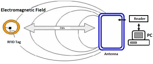
A reader comprises a Radio Frequency Module and an antenna that creates high-frequency electromagnetic fields. The tag, on the other hand, is a passive device that doesn’t have a battery. It contains a microchip to store and process information and an antenna that transmits and receives signals.
The reader can read the information on tags by placing them near them. The electromagnetic field generated by the reader causes electrons to travel through the tag’s antenna, thereby powering the chip.
The tag’s powered chip then sends its stored information back via another radio signal to the reader. This is known as backscatter. Backscatter is a change in electromagnetic/RF waves. The reader detects this and interprets it.
Hardware Overview – RC522 RFID Reader/Writer Module
The RC522 RFID module-based MFRC522 IC by NXP can be purchased online for as low as four dollars. The module usually includes an RFID card tag and a key fob tag with 1KB of memory. It can also write a tag so that you can keep some secret message inside.
The RC522 RFID Reader Module is designed to create 13.56MHz electromagnetic fields that it uses for communication with RFID tags (ISO 14443A standards tags). The 4-pin Serial Perimeter Interface allows the reader to communicate with a microcontroller. SPI) with a maximum data speed of 10Mbps. It supports communication via UART and I2C protocols.
An interrupt pin is included with the module. This is useful because it allows you to ask the module, “Is there any card in view?” The module will notify us when a tag is within its range.
The module operates at a voltage of 2.5V to 3.3VThe good news is that there are many other options. 5-volt tolerance allows logic pins to be connected to an Arduino or 5V logic microcontroller using a standard connector.
These are the specifications complete:
| Frequency range | 13.56 MHz ISM Band |
| Host Interface | SPI/I2C/UART |
| The voltage of Operating Supply | From 2.5 V to 3.0 V |
| Maximum. Max. | 13-26mA |
| Min. Min. | 10uA |
| Logic Inputs | 5V Tolerant |
| Read Range | 5 cm |
Contents of the Kit
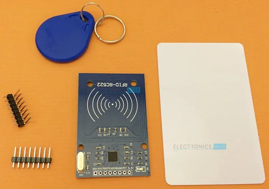
The RC522 RC522 Reader Kit includes the RC522 RF522 RFID Module, RFID Card, RFID Key Fob, and a few male headers to solder. The RFID tags, i.e., RFID Card and RDIF Key Fob in this kit, are compatible with MIFARE 1K tags (each has 1 KB memory).
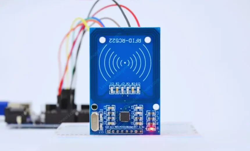
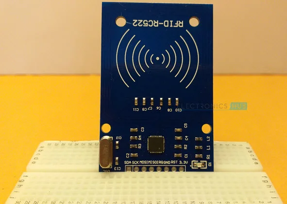
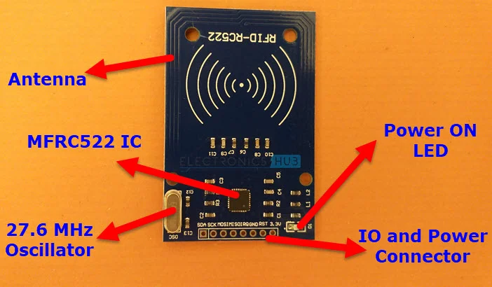
The RC522 RFID Reader module consists of the MFRC522 IC, a 27.12 MHz crystal oscillator, an Antenna embedded in the PCB, and supporting passive components emitting a 13.56 MHz electromagnetic force.
It is important to note that while the MFRC522 IC can operate at a voltage range of 2.5V to 3.3V, the communication pins can withstand 5V. The power supply voltage should not exceed 3.3V. However, you can connect the data pins directly to Arduino.
RC522 RFID Module Pinout
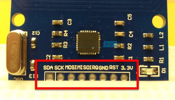
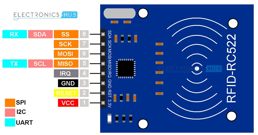
Eight pins interface the RC522 module to the outside world. These connections are:
VCC powers the module. It can range from 2.5 to 3 volts. It can be connected to the 3.3V output of your Arduino. It is important to remember that connecting it to the 5V pin can cause damage to your module.
RST stands for Reset and Power-down. This pin is used to enable hard power-down when it goes low. This will turn off all internal current sinks, including the oscillator. The input pins are also disconnected from the outside. The module will be reset at the rising edge.
GND, the Ground Pin, must be connected to the Arduino’s GND pin.
The interrupt pin IRQ can alert the microcontroller if an RFID tag is within its range.
When the SPI interface has been enabled, the MISO/SCL/Tx pin acts master-in-slave-out. It acts as a serial clock when the I2C interface has been enabled. It also acts as a serial data output when enabled by the UART interface.
MOSI (Master Outslave In) refers to SPI input to the RC522 module.
SCK (Serial Counter) can accept clock pulses from the SPI bus Master, i.e. Arduino.
SS/SDA/Rx acts as signal input when the SPI interface is active. It also acts as serial input for the I2C interface enabled. This pin can be marked by wrapping it in a square to make it easy to identify the others.
RC522 Pin Configuration
| Pin Number | Pin Name | Description |
| 1 | Vcc | Used to power the module. Typically, 3.3V is used |
| 2 | RST | Reset pin – Used to power down or reset the module |
| 3 | Ground | The system is connected to ground |
| 4 | IRQ | Interrupt pin – Used to wake the module up when a device is in range |
| 5 | MISO/SCL/Tx | When used for SPI communication MISO pin acts as SCL to I2c or Tx for UART. |
| 6 | MOSI | Pin for SPI communication Master or slave |
| 7 | SCK | Serial clock pin – Used to supply clock source |
| 8 | SS/SDA/Rx | Serves as serial input (SS), for SPI communication, SDA during IIC and Rx |
RC522 Features
- 13.56MHz RFID module.
- Operating voltage: 2.5V to 3.0V.
- Communication: I2C protocol and SPI.
- Maximum data rate: 10Mbps.
- Range of Readability: 5cm.
- Current Consumption: 13 to 26mA.
- Power down mode consumption 10uA (min).
Components Required for rfid rc522 arduino
- Arduino UNO
- RC522 RFID Module
- RFID Tags (card and key fob in the kit)
- Connecting Wires
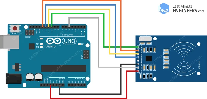
Connecting RC522 RFID module to Arduino UNO
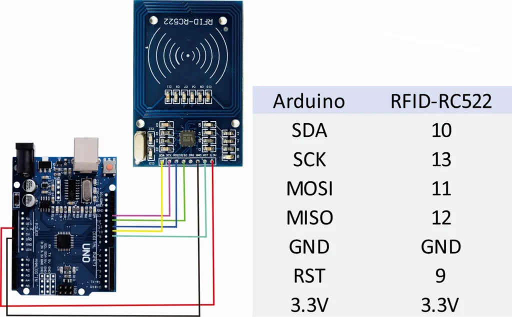
We now have all the information to hook it up to our Arduino. Connect the VCC pin of the module to 3.3V on Arduino. The GND pin should be connected to the ground. You can connect the pin RST to any digital pin on Arduino. It is connected to digital pin #5. Because the Arduino library that we will use doesn’t support IRQ, it is not connected.
We are now left with the pins used for SPI communication. The RC522 module requires a lot of data transfer so it will perform best when connected to the hardware SPI pins of a microcontroller. The hardware SPI pins perform faster than “bit-banging” the interface code with another set of pins.
Each Arduino board has its own SPI pins, so you should connect them accordingly. These pins correspond to the UNO/Nano board V3.0. They are digital 13 (SCK), 12, (MISO), 11, (MOSI), and 10 (SS).
The pins for a Mega are different. Digital 50 (MISO), 51(MOSI), 52, SCK and 53 (SS) are the best options. For a quick overview, refer to the table below.
| MOSI | MISO | SCK | CS | |
| Arduino Uno | 11 | 12 | 13 | 10 |
| Arduino Nano | 11 | 12 | 13 | 10 |
| Arduino Mega | 51 | 50 | 52 | 53 |
If you are using an Arduino board other than the one listed above, it is recommended to consult the official documentation of Arduino before proceeding.
You are now ready to go once you have everything in order!
Arduino Code Reading rfid rc522 arduino Tag
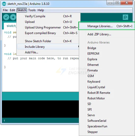
It’s a lot of work to communicate with the RC522 RFID Module. But luckily, there is a library called MFRC522 library. This makes it easier to read and write RFID tags.
Visit the website to download the library GitHub repo, click the button below to download the zip. rfid-master.zip
Open Arduino IDE and go to Sketch > Include Library >Add. Zip Library and then the RFID-master.zip file you downloaded. This Installing an Arduino library tutorial will provide more information.
After you have installed the library, open the Examples menu and select MFRC522> Dump Info example sketch.
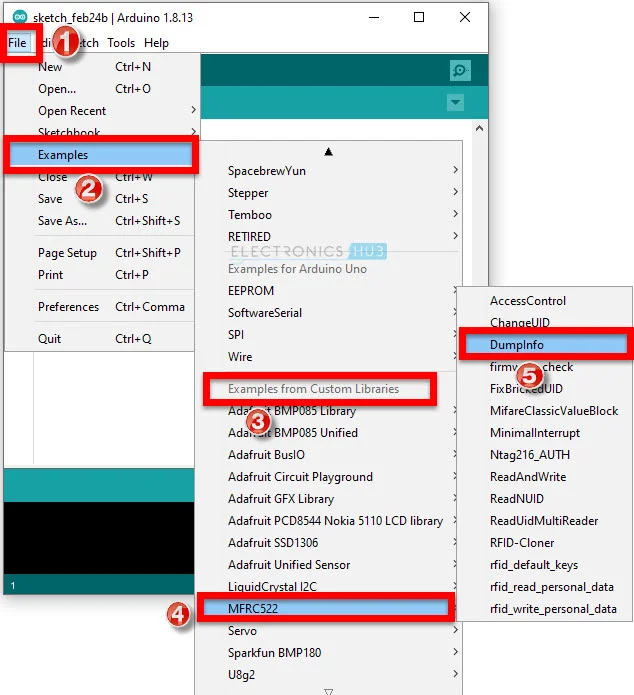
This sketch won’t write any data to the tag. This sketch will only tell you if it was able to read the tag and display some information about it. This is a great way to check if you have a tag that has been successfully read
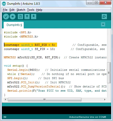
Start at the beginning of your sketch. RST_PIN Correctly initialized. In our case, we are using digital pin #5, so change it back to 5.
Now upload the sketch to the Serial Monitor. You’ll likely see the following when you move the tag closer towards the module. You should not move the tag before all information has been displayed
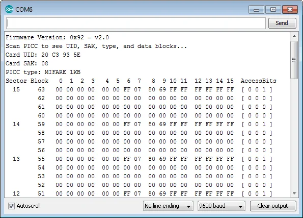
It contains all information regarding the tag, including the Unique ID (UID) and the total 1K memory.
MIFARE Classic 1K Memory Layout
Each 1K of memory in the Tag is divided into 16 sections (from 0 through 15). Each sector is subdivided into four blocks (blocks 0 through 3). Each block can store 16 bytes (from 0 through 15). This tells us that we can do so.
16 sectors x 4 blocks x 16 bytes of data = 1024 bytes = 1K memory
Below is highlighted the entire 1K memory, including sectors, blocks, data, and data.
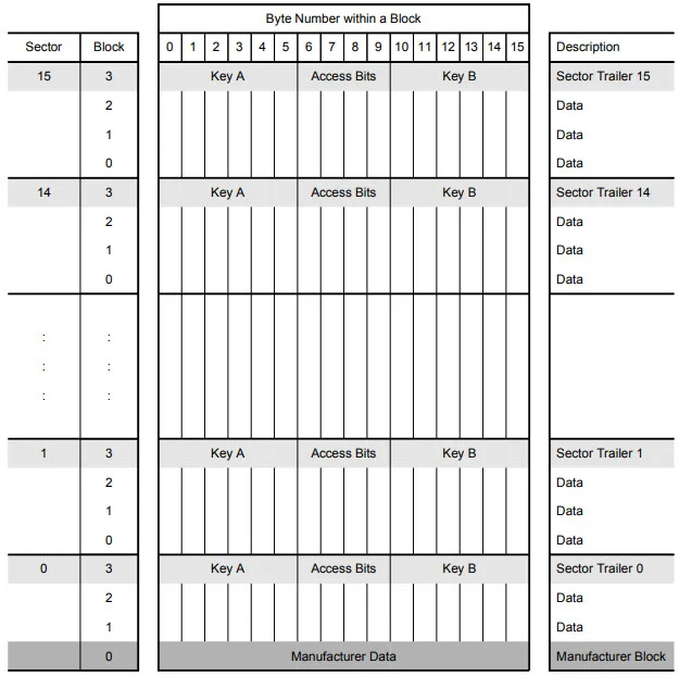
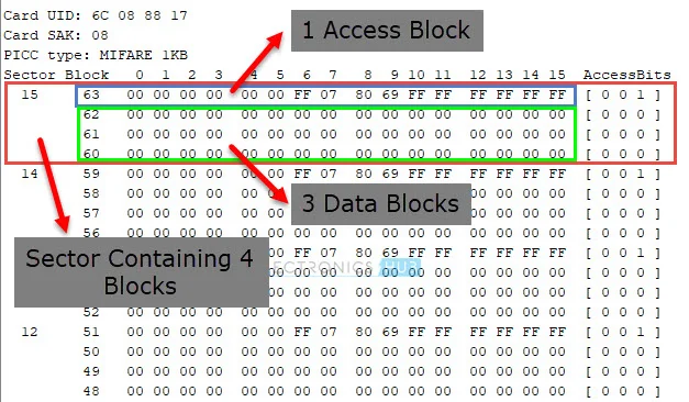
Each sector’s block three is called a sector Trailer and contains information called access Bits to grant read-write access to the remaining blocks of an industry. Only the top 3 blocks (blocks 0, 1, and 2) in each sector are available for data storage. We have 48 bytes per 64-byte section available for our use.
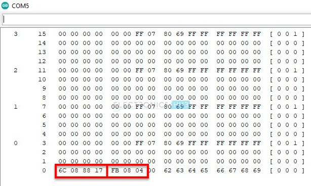
Also, Sector 0 Block 0 is known as manufacturer Block/Manufacturer information containing the IC manufacturer information and the unique identifier(UID). Below, the Manufacturer Block is highlighted in red.
Arduino Code Writing with rfid rc522 arduinoTag
We’ll now move to the next experiment, as you have successfully read and interpreted the RFID tag. This sketch will show you how to add custom data to an RFID tag. Before we get into the details, you can try out the sketch.
#include <SPI.h> //include the SPI bus library
#include <MFRC522.h> //include the RFID reader library
#define SS_PIN 10 //slave select pin
#define RST_PIN 5 //reset pin
MFRC522 mfrc522(SS_PIN, RST_PIN); // instatiate a MFRC522 reader object.
MFRC522::MIFARE_Key key; //create a MIFARE_Key struct named ‘key’, which will hold the card information
//this is the block number we will write into and then read.
int block=2;
byte blockcontent[16] = {“Last-Minute-Engg”}; //an array with 16 bytes to be written into one of the 64 card blocks is defined
//byte blockcontent[16] = {0,0,0,0,0,0,0,0,0,0,0,0,0,0,0,0}; //all zeros. This can be used to delete a block.
//This array is used for reading out a block.
byte readbackblock[18];
void setup()
{
Serial.begin(9600); // Initialize serial communications with the PC
SPI.begin(); // Init SPI bus
mfrc522.PCD_Init(); // Init MFRC522 card (in case you wonder what PCD means: proximity coupling device)
Serial.println(“Scan a MIFARE Classic card”);
// Prepare the security key for the read and write functions.
for (byte i = 0; i < 6; i++) {
key.keyByte[i] = 0xFF; //keyByte is defined in the “MIFARE_Key” ‘struct’ definition in the .h file of the library
}
}
void loop()
{
// Look for new cards
if ( ! mfrc522.PICC_IsNewCardPresent()) {
return;
}
// Select one of the cards
if ( ! mfrc522.PICC_ReadCardSerial())
{
return;
}
Serial.println(“card selected”);
//the blockcontent array is written into the card block
writeBlock(block, blockcontent);
//read the block back
readBlock(block, readbackblock);
//uncomment below line if you want to see the entire 1k memory with the block written into it.
//mfrc522.PICC_DumpToSerial(&(mfrc522.uid));
//print the block contents
Serial.print(“read block: “);
for (int j=0 ; j<16 ; j++)
{
Serial.write (readbackblock[j]);
}
Serial.println(“”);
}
//Write specific block
int writeBlock(int blockNumber, byte arrayAddress[])
{
//this makes sure that we only write into data blocks. Every 4th block is a trailer block for the access/security info.
int largestModulo4Number=blockNumber/4*4;
int trailerBlock=largestModulo4Number+3;//determine trailer block for the sector
if (blockNumber > 2 && (blockNumber+1)%4 == 0){Serial.print(blockNumber);Serial.println(” is a trailer block:”);return 2;}
Serial.print(blockNumber);
Serial.println(” is a data block:”);
//authentication of the desired block for access
byte status = mfrc522.PCD_Authenticate(MFRC522::PICC_CMD_MF_AUTH_KEY_A, trailerBlock, &key, &(mfrc522.uid));
if (status != MFRC522::STATUS_OK) {
Serial.print(“PCD_Authenticate() failed: “);
Serial.println(mfrc522.GetStatusCodeName(status));
return 3;//return “3” as error message
}
//writing the block
status = mfrc522.MIFARE_Write(blockNumber, arrayAddress, 16);
//status = mfrc522.MIFARE_Write(9, value1Block, 16);
if (status != MFRC522::STATUS_OK) {
Serial.print(“MIFARE_Write() failed: “);
Serial.println(mfrc522.GetStatusCodeName(status));
return 4;//return “4” as error message
}
Serial.println(“block was written”);
}
//Read specific block
int readBlock(int blockNumber, byte arrayAddress[])
{
int largestModulo4Number=blockNumber/4*4;
int trailerBlock=largestModulo4Number+3;//determine trailer block for the sector
//authentication of the desired block for access
byte status = mfrc522.PCD_Authenticate(MFRC522::PICC_CMD_MF_AUTH_KEY_A, trailerBlock, &key, &(mfrc522.uid));
if (status != MFRC522::STATUS_OK) {
Serial.print(“PCD_Authenticate() failed (read): “);
Serial.println(mfrc522.GetStatusCodeName(status));
return 3;//return “3” as error message
}
//reading a block
byte buffersize = 18;//we need to define a variable with the read buffer size, since the MIFARE_Read method below needs a pointer to the variable that contains the size…
status = mfrc522.MIFARE_Read(blockNumber, arrayAddress, &buffersize);//&buffersize is a pointer to the buffersize variable; MIFARE_Read requires a pointer instead of just a number
if (status != MFRC522::STATUS_OK) {
Serial.print(“MIFARE_read() failed: “);
Serial.println(mfrc522.GetStatusCodeName(status));
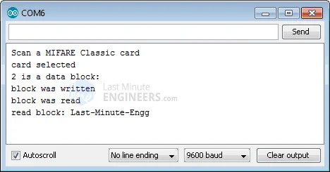
return 4;//return “4” as error messageThis is the output of the serial monitor.
}
Serial.println(“block was read”);
}The output on the serial monitor will look like this
Code Explanation for rfid rc522 arduino
The sketch begins by including the MFRC522 & SPI library, defining Arduino pins to which RC522 can be connected, and invoking the MFRC522 reader object.
Next, define the block where we will store our data. This is sector 0 blocks 2. Never select block 3 in any industry. Blocks written into a “sector trailer” block may not be usable.
#include <SPI.h>//include the SPI bus library
#include <MFRC522.h>//include the RFID reader library

#define SS_PIN 10  //slave select pin
#define RST_PIN 5  //reset pin
MFRC522 mfrc522(SS_PIN, RST_PIN);        // instatiate a MFRC522 reader object.
MFRC522::MIFARE_Key key;//create a MIFARE_Key struct named 'key', which will hold the card information
Next, define the block where we will store our data. This is sector 0 block 2. Never select block 3 in any sector. Blocks written into the ‘sector trailer block’ can be rendered unusable.
//this is the block number we will write into and then read.
int block=2;
Next, create an array of 16 bytes called blockcontent[16] that holds the message you want to put into the block. Any block can be deleted by adding zeros.
byte blockcontent[16] = {"Last-Minute-Engg"};  //an array with 16 bytes to be written into one of the 64 card blocks is defined
//byte blockcontent[16] = {0,0,0,0,0,0,0,0,0,0,0,0,0,0,0,0};  //all zeros. This can be used to delete a block.
Next, define an array of 18 bytes called readbackblock[18]. This is used to read back the written contents. Wait…18 bytes? This should be 16 bytes. The answer is no. To hold 16 bytes of data, the buffer used by MIFARE_Read in the MFRC522 library must be at least 18 bytes.
//This array is used for reading out a block.
byte readbackblock[18];
In the Setup function, we initiate serial communications with the computer, the SPI library, and the MFRC522 object. Also, we must prepare the security key to enable the read and write functions. All six key bytes should be set to 0xFF.
The keys still need to be defined, and this kit’s cards are brand new. They are, therefore, 0xFF. We would need the key to access a card programmed by another person. The key would need to be kept in the ‘key’ folder.
Serial.begin(9600);        // Initialize serial communications with the PC
SPI.begin();               // Init SPI bus
mfrc522.PCD_Init();        // Init MFRC522 card (in case you wonder what PCD means: proximity coupling device)
Serial.println("Scan a MIFARE Classic card");

// Prepare the security key for the read and write functions.
for (byte i = 0; i < 6; i++) {
   key.keyByte[i] = 0xFF;  //keyByte is defined in the "MIFARE_Key" 'struct' definition in the .h file of the library
Loop function: We first scan the card to see if it is visible. If yes, then that card is chosen for writing and/or reading purposes.
// Look for new cards
  if ( ! mfrc522.PICC_IsNewCardPresent()) {
    return;
  }

  // Select one of the cards
  if ( ! mfrc522.PICC_ReadCardSerial())
  {
    return;
  }
  Serial.println("card selected");
It is easy to wring the block. All we need is a custom function called createBlock() that takes two parameters – one being the block number to which the data is to be written and the other the data itself.
//the blockcontent array is written into the card block
writeBlock(block, blockcontent);
We need to check that the write operation succeeded by reading the contents of the block back. You can do this using a custom function called readBlock(). This takes two parameters: one is the block number, and another is an array to store block contents. If you need to view the entire 1k of memory, with the block stored into it, the PICC_DumpToSerial() function can be used.
//read the block back
readBlock(block, readbackblock);
//uncomment below line if you want to see the entire 1k memory with the block written into it.
//mfrc522.PICC_DumpToSerial(&(mfrc522.uid));
Finally, we print the contents from readbackblock array using for loops and display them on a serial monitor.
//print the block contents
 Serial.print("read block: ");
 for (int j=0 ; j<16 ; j++)
 {
   Serial.write (readbackblock[j]);
 }
 Serial.println("");
Conclusion
This guide is for beginners to the MFRC522 IC-based RC522 Reader Module. This guide will teach you about the RC522 module, how to interface Arduino with RC522, and how to read data from an RFID tag.