
This article is all about the two-way switch wiring works types and examples. Before moving forward, let’s know what kind of Switch it is. It’s also known as a Staircase Switch. For example, a single bulb is controlled by two switches on either side of the Staircase.
Warning: This article is just for increasing a person’s knowledge or a theory about the 2 Way Switch. It’s not an installation guide. If you plan to install this setup at your house, you must consult an expert as this setup includes a 230V AC supply or depends on where you live.
As we know, Switches are parts of our daily lives; we use them everywhere, even if it’s used 24/7. They are fixed in our homes, offices, cars, Industries, and many other places. It’s also used in gadgets that are used several times a day. For example, mobile phones, laptops, computers, etc. They all consist of multiple switches.
The Switch is an electrical device used for the ON and OFF of an electric circuit.
TYPES:
Numerous types of Switches are used according to the situation and place of installation. Some of these types are;
All types of Switches play the same role of either shutting the flow of electricity or changing the flow of power supply. They “make” or” break” the circuit.
Switches are commonly used to turn ON and OFF the lights, fans, etc. A standard Switch is used in these electrical devices, but a unique switch is known as the “Way Switch,” which is used explicitly for fixing Staircase lighting.
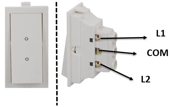
It’s further explained with a different topic, such as the elements of the 2 Way Switch types of wires used in it. Usually, a Way Switch is a single pole with three terminals.
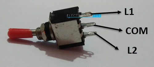
These three terminals are COM, L1, and L2, and casually, the terms COM, 1 Way, and 2 Way are used. COM and L1 terminals are connected, and in another case, COM and L2 terminals are connected.
These types of connections are named as “Break before make” design. It works in such a manner that the first connection is broken to create or make another connection. It’s also similar to a simple Two Terminals Switch, a make and brake device.
The given image presents the most used two-way Switch commonly used in households.
How to Wire a 2-Way Switch?
As mentioned above in the “Introduction” paragraph, the use of a two-way switch with an example of Staircase lighting, as lights can be turned ON at the start of stairs and then at the end of the stair, lights can be turned OFF, simply by Toggling the Switch near the top of Staircase.
Many ways show the importance of Two two-way switch connections. There’s also a traditional method that is not used nowadays as time has brought many changes. Another method is the modern and safest one, commonly used in Industries and household appliances. Given below is the Wiring method for a way Switch connection.
Standard 2-Way Switch Wiring
A few Two Way light Switches are connected with three-wire control in the Standard Way of wiring. Given below is the image of the Standard way of Wiring.
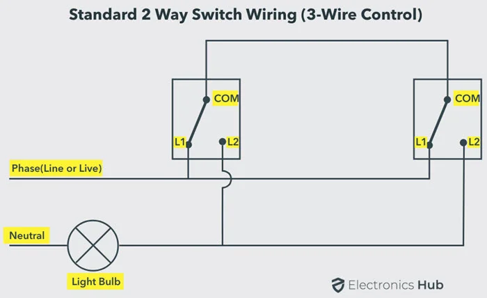
From the above diagram, both COM terminals’ position is observed and connected. The L1 terminal of both switches is connected to the AC supply inline form or design. Still, the L2 terminal of the buttons is attached to one side terminal of the light bulb while the other terminal is connected to the neutral AC power supply.
From the above diagram, the terminal’s position and working of wiring can be easily studied. In the above-shown image, switches are in the default state, and the light is OFF. If any of the switches are toggled, then the lights turn ON.
FOR EXAMPLE:
From the above image, COM is connected to L1 terminals to turn the lights on. If the COM terminal of switch1 is separated or disconnected, then the COM of switch1 will connect to the L2 terminal. After these changes, the circuit’s path will be completed, and the lights will be turned ON.
Now, Switch and Switch two are Toggled to turn off the lights, and these actions cut off the power flow to the sunlight. There are some possibilities in which they will turn ON. Only two options are given below:
- COM of Switch 1 is connected to L1, and COM of Switch is connected to L2.
- COM of Switch 1 is connected to L2, and COM of Switch is connected to L1.
When comparing this setup with the Digital electronics, this setup is similar to EX-OR Gate, as in this setup, the light status (ON and OFF) depends on the COM terminals’ connection with both L1 and L2 terminals.
The given table shows the connections of Standard Wiring and clearly shows the status of lights when COM terminals are connected to L1 and L2 terminals.
| Switch 1 COM (connected to) | Switch 2 COM (connected to) | Status of Light |
|---|---|---|
| L1 | L1 | OFF |
| L1 | L2 | ON |
| L2 | L1 | ON |
| L2 | L2 | OFF |
This method is preferred when both lines and neutral wires come from the same lighting circuit, and it should also be known that this method uses more wires.
Alternative Method of Two-Way Switch Wiring
This Alternative Method of Two Switch Wiring is the oldest, mostly found in ancient houses and Industrial constructions. It’s also known as Two Wire Control Wiring.
This wiring setup is not preferred for modern constructions, and if you have decided to renovate the wiring setup, then the Standard Wiring method should be used instead of this one.
This wiring setup is just an explanation for knowledge purposes, and its drawbacks are also explained. The diagram shows the Methods of implementation of the Alternative Two Way Switch.
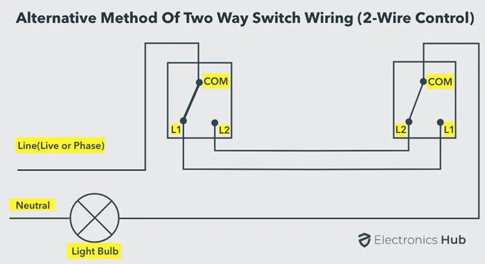
For further explanation of the diagram:
L1 and L2 terminals are linked parallel with each other in both switches, then the COM terminal of the first is linked to phase, the second COM terminal one side is attached to the light bulb, and the other side is connected to the neutral AC supply.
When the bulb is OFF, then the state of the bulb is known to be the default state. When one of the switches is moved or changed, the state of the bulb changes, and the light turns ON. This setup is similar to the EX-NOR Gate.
The given table shows the wiring method for the Alternative Two Way Switch.
| Switch 1 COM (connected to) | Switch 2 COM (connected to) | Status of Light |
|---|---|---|
| L1 | L1 | ON |
| L1 | L2 | OFF |
| L2 | L1 | OFF |
| L2 | L2 | ON |
This method uses useless wires, and it’s not recommended anymore as the Phase and Neutral may come from separate lighting circuits.
Another fault in this method is electromagnetic radiation, as we had studied that any conductor produces electromagnetic radiation. Now consider the Live and neutral wires are fixed close to each other, then they will cancel each other EM Radiations.
But in the Alternative wiring method, the Live and Neutral are implemented separately in different parts of the construction sites, making a big loop. This will cause other problems, such as interfering with EM and RF signals.
Example:
Using the given products:
1: Single Pole Double Throw (SPDT)
2: Toggle Switches
3: An LED
The material that is important for a two-way switch is the SPDT. This can be used as Two Way light switch as it consists of 3 terminals and works similarly to a two-way switch.
The given diagram shows a casual SPDT Toggle and its terminals.
NOTE: This example is self-created. It’s not given anywhere. The example material is collected based on their functions for making the switch, and for this example, the Standard Way of Wiring is selected. For the first method, the 3-wire control is used with a 3.7 V Lithium-ion Battery for the power supply, and it works perfectly.
Conclusion
After reading this article, you will be able to understand two-way switch wiring and its methods. For any difficulty, comment below and also tell us your thoughts about this article.